
How to assemble your Waterfowl Keyboard kit
21 Feb 2023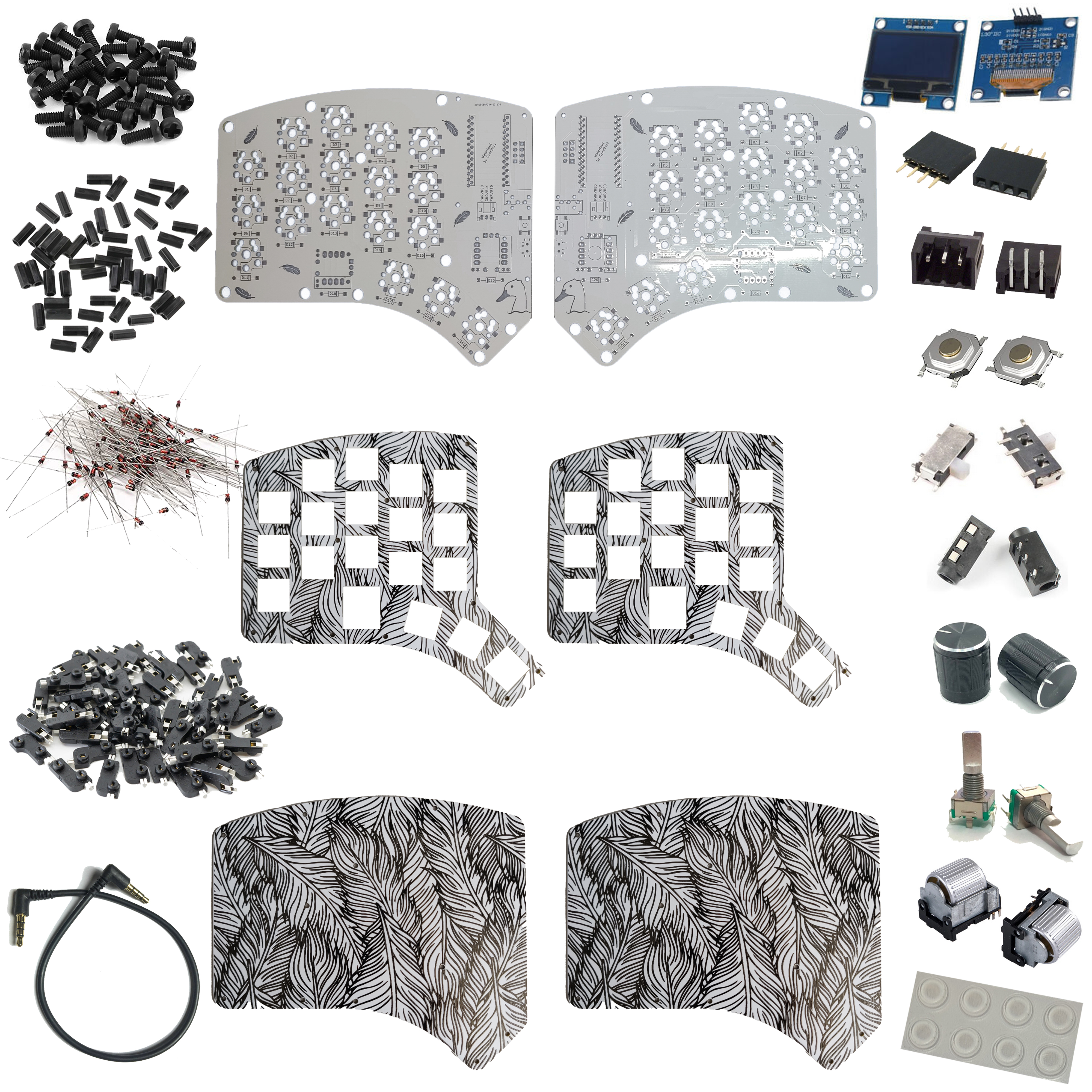
Your kit contains
- Waterfowl PCBs x 2
- Switch plates x 2
- Bottom plates x 2
- 4mm M2 screws x 50
- 8mm M2 standoffs x 22
- Through hole diodes x 40
- Kailh hotswap sockets x 36
- TRRS cable
- OLED displays x 2
- OLED sockets x 2
- Battery sockets x 2
- Reset switches x 2
- Power switches x 2
- TRRS jacks x 2
- Encoder knobs x 2
- Rotary encoders x 2
- Roller encoders x 2
- Rubber feet x 8
Tools you will need
- Soldering iron + solder
- Small Phillips head screwdriver
- Flush cutters for trimming diode legs
Diodes
Placement
The diodes can be soldered to either side of the PCB. For the cleanest look, solder them to the underside.
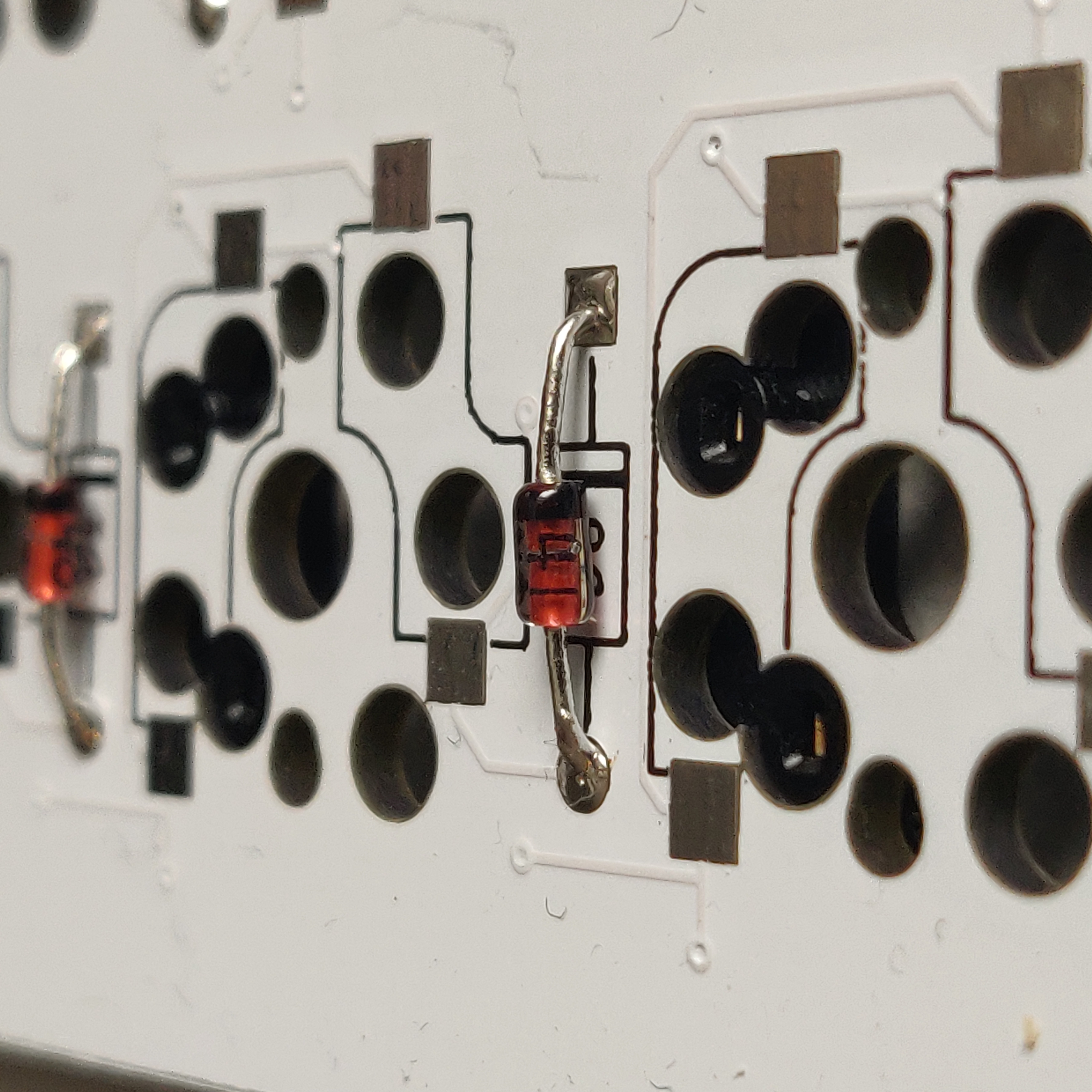
Feed both legs of a diode through the diode holes in the PCB, you can use a square object to help bend the legs at a right angle.
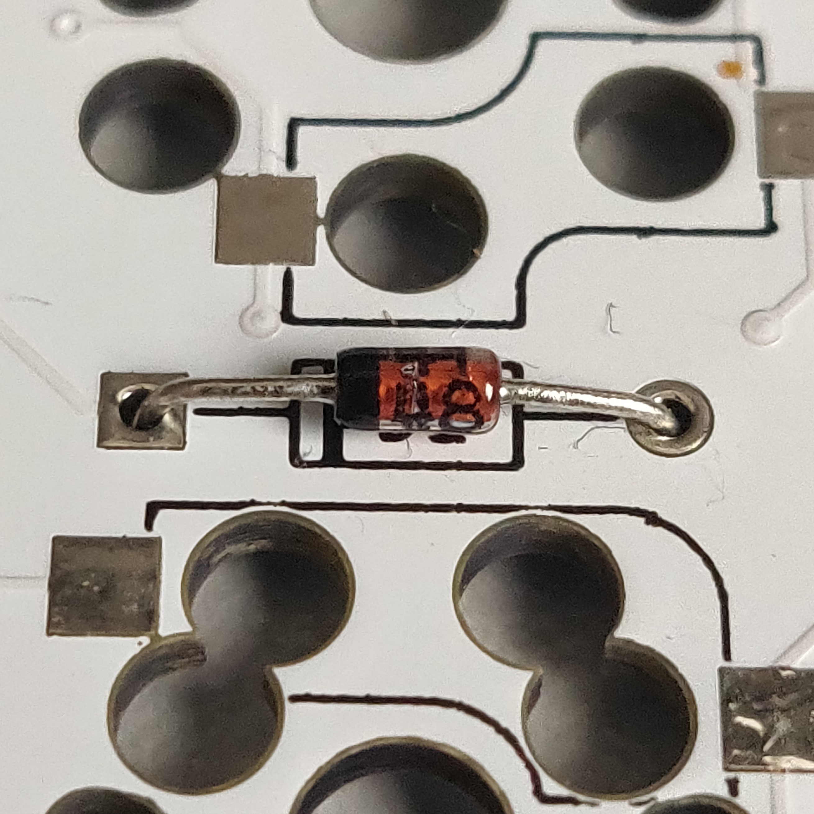
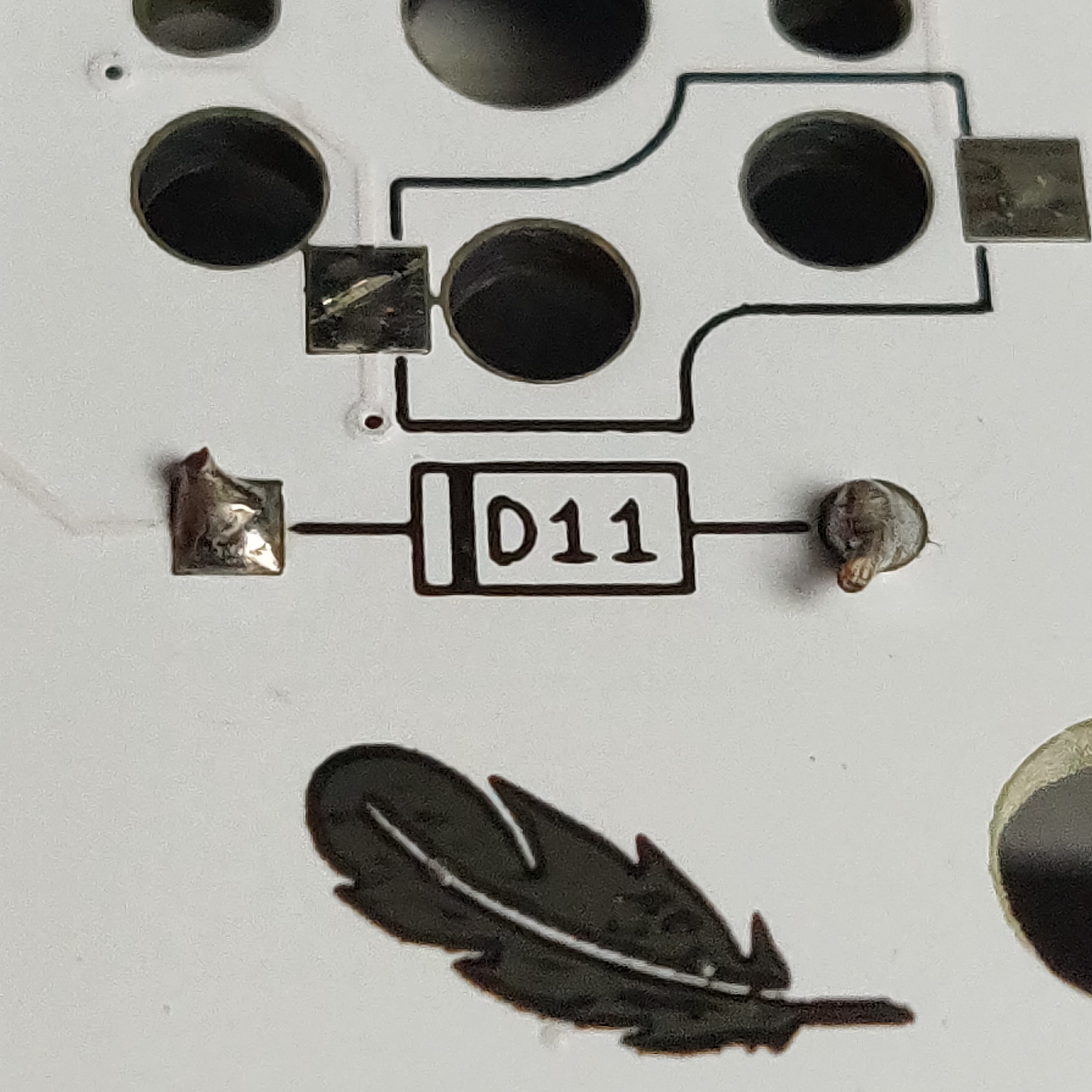
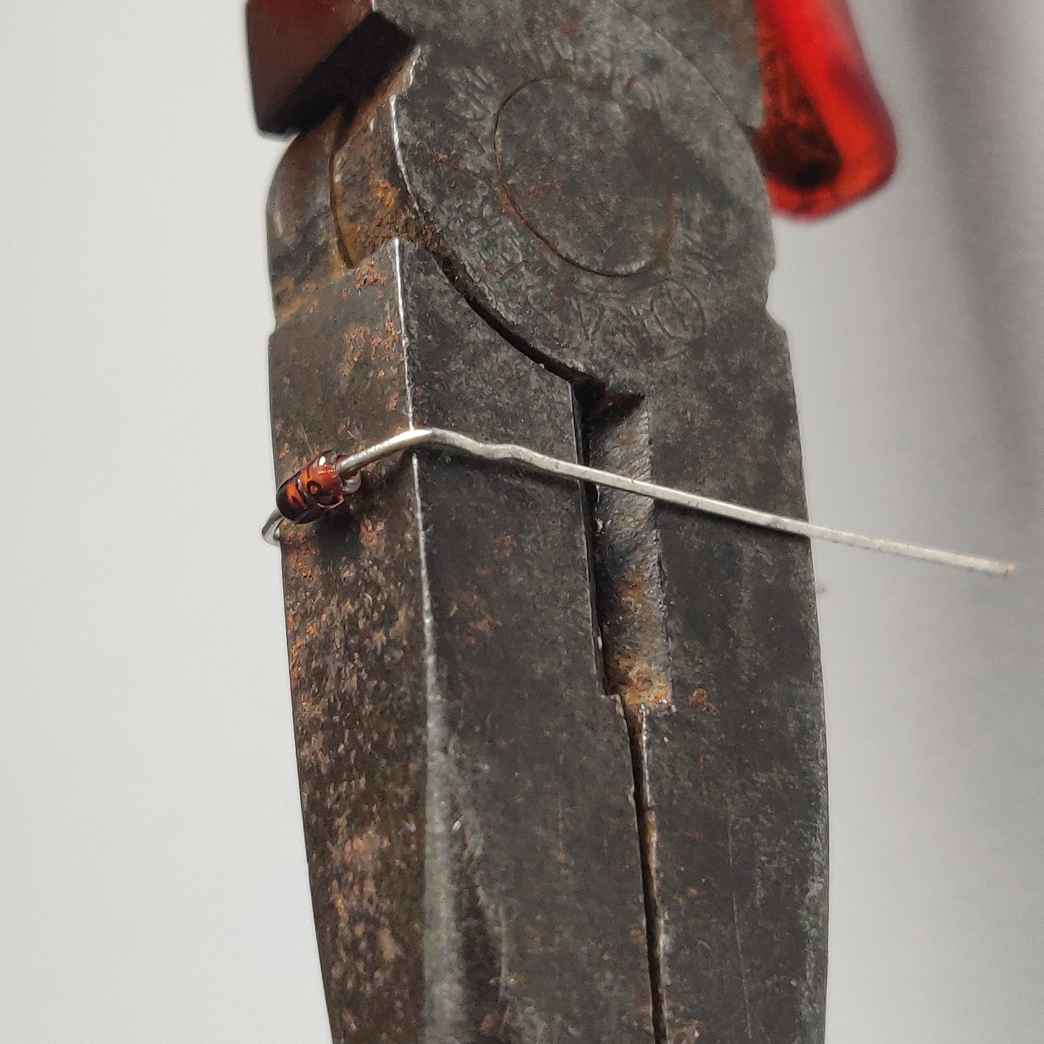 Each diode has a black bar on one end of the glass. This is the Cathode side of the Diode.
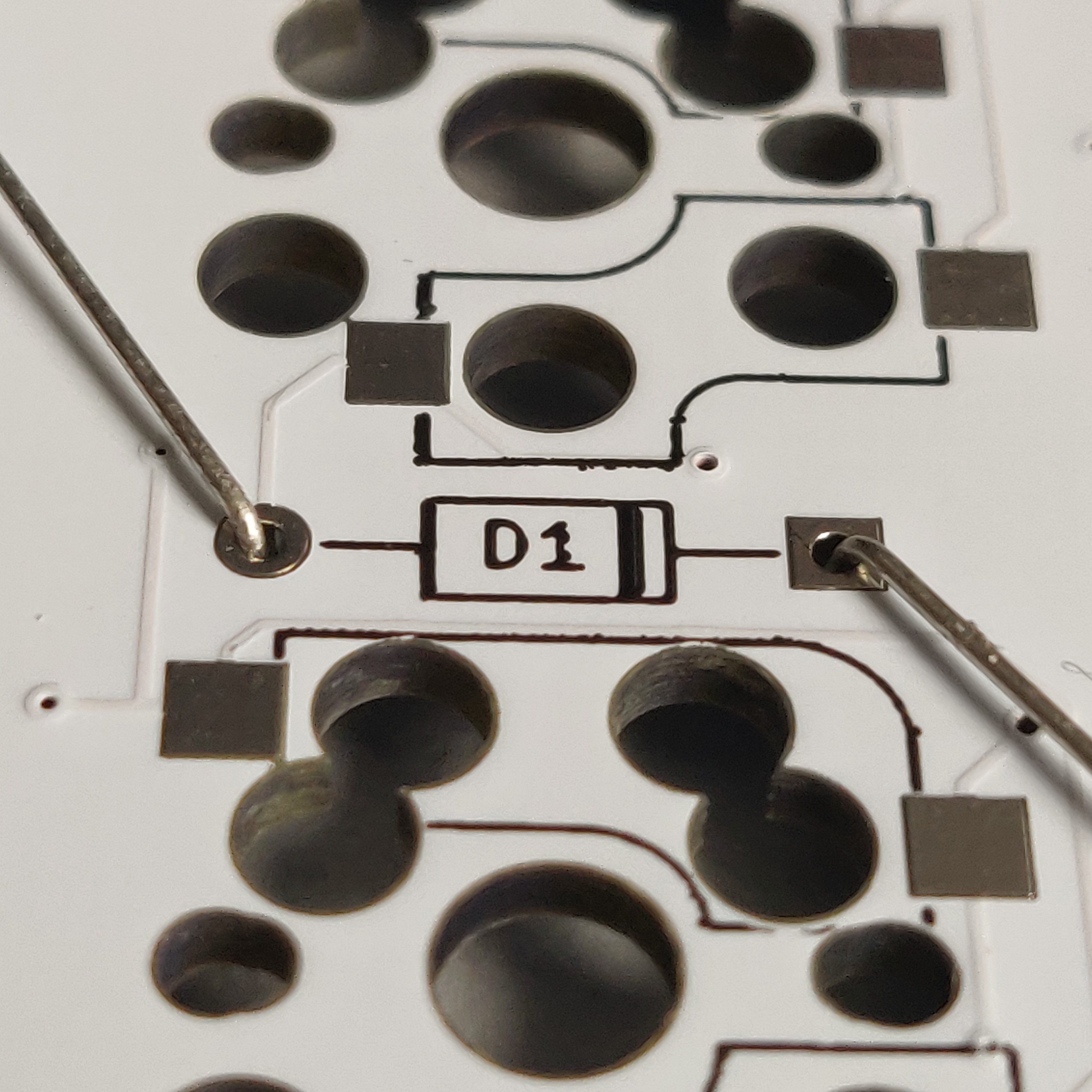
Make sure that the black mark on the diode is aligned with the black line on the PCB as well as the square shaped pad.
 You can bend the legs on the other side of the PCB to keep the diodes in place while soldering.
Soldering
Place the tip of the soldering iron onto the pad so that it heats up both the leg of the diode and the pad.
Add a small amount of solder and let it flow around the connection.
Once cooled, use your cutters to snip off the excess diode legs.
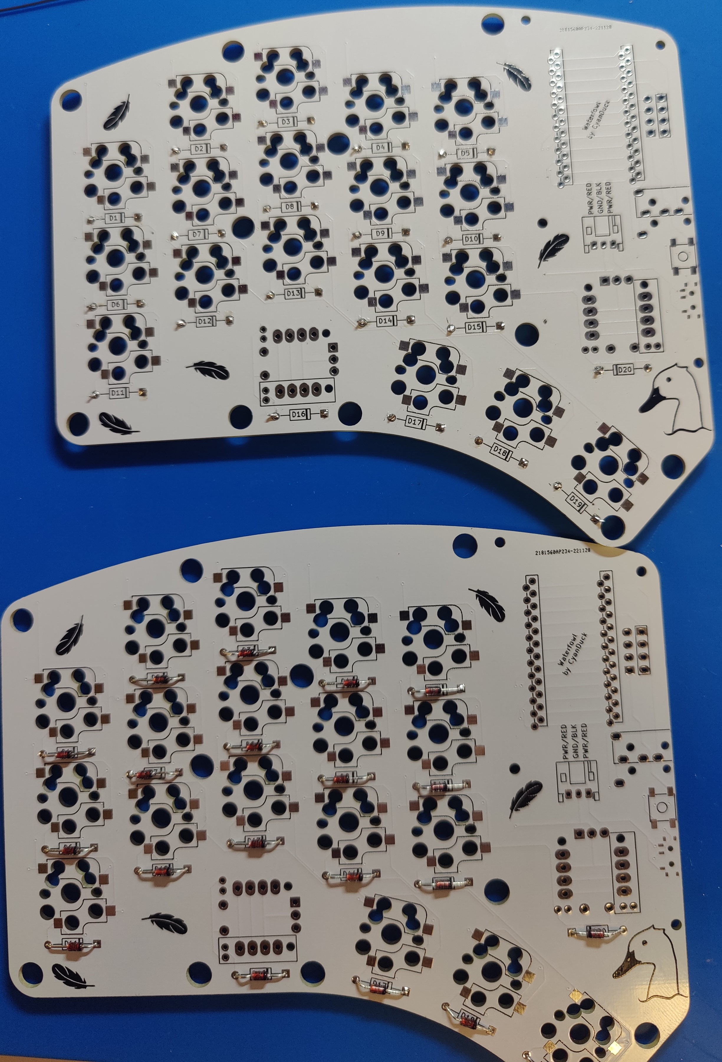
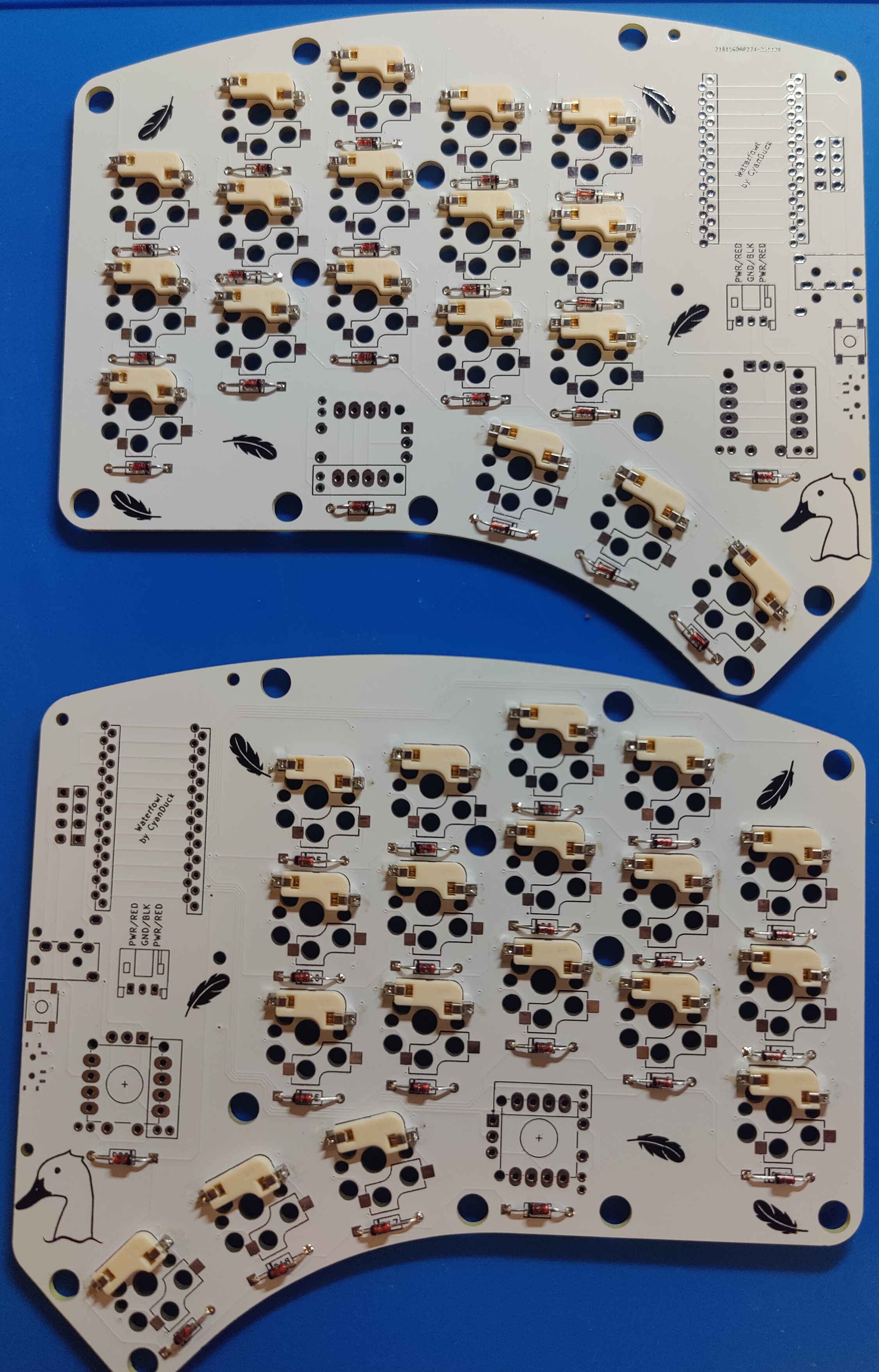
After soldering all 40 diodes, your PCB should look like this:
Hotswap sockets
If you’ve never soldered hotswap sockets before, this is a great video to help you out!
Summary
Each switch needs a hotswap socket, they need to be soldered to the underside of the PCB.
Begin by putting some solder on one of the pads.
Then place the hotswap socket into the holes, so that one of its contacts is now resting on the pad you soldered.
Use some tweezers to apply pressure to the socket, while heating up the contact and allowing the solder to flow into it.
To solder the other side, push the iron into the contact, heating up the socket and the pad on the PCB for a few seconds. Then add some solder into the contact making sure that it flows through and makes a solid connection.
After soldering all 36 hotswap sockets, your PCB should look like this:
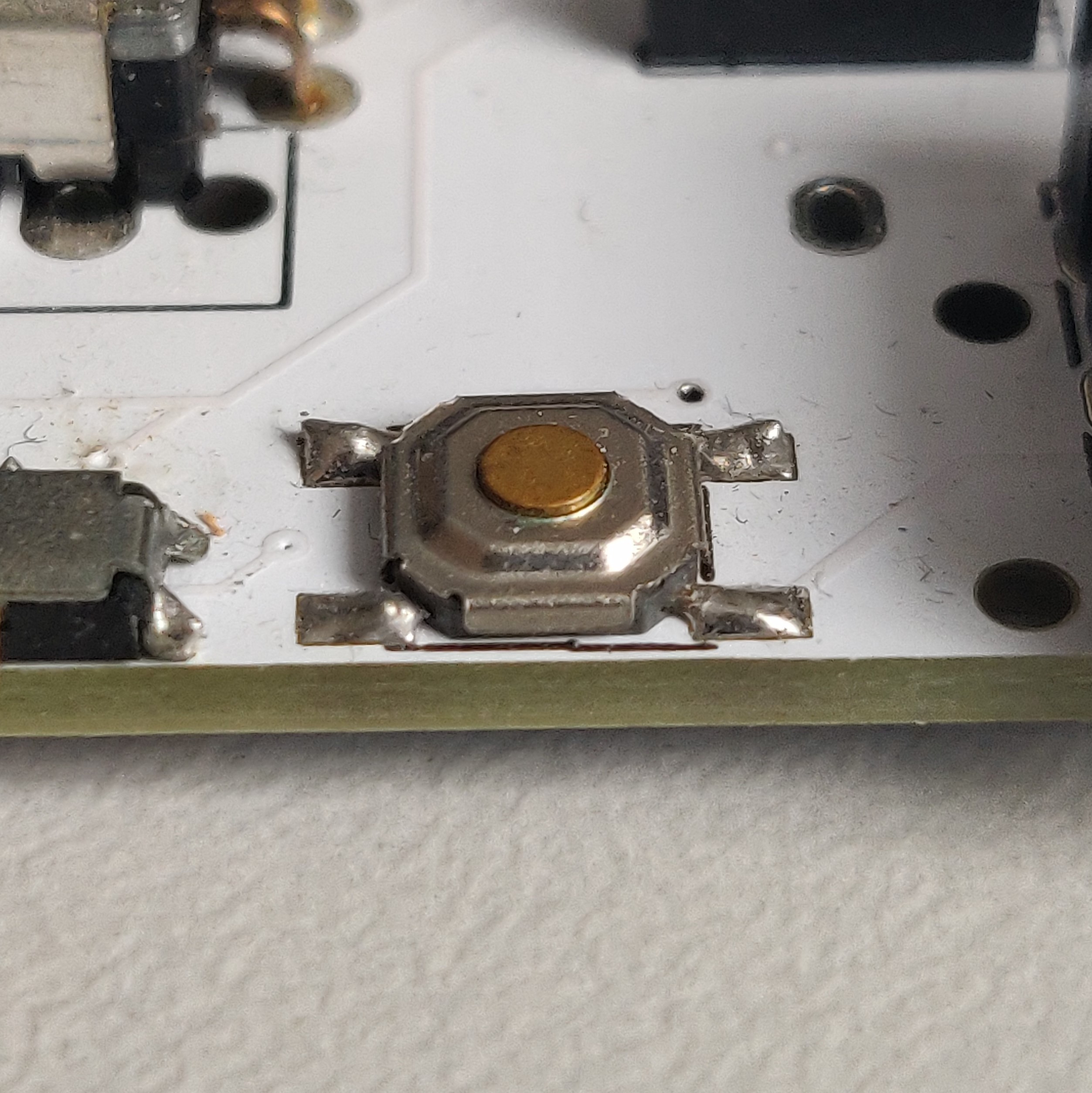
Reset switches
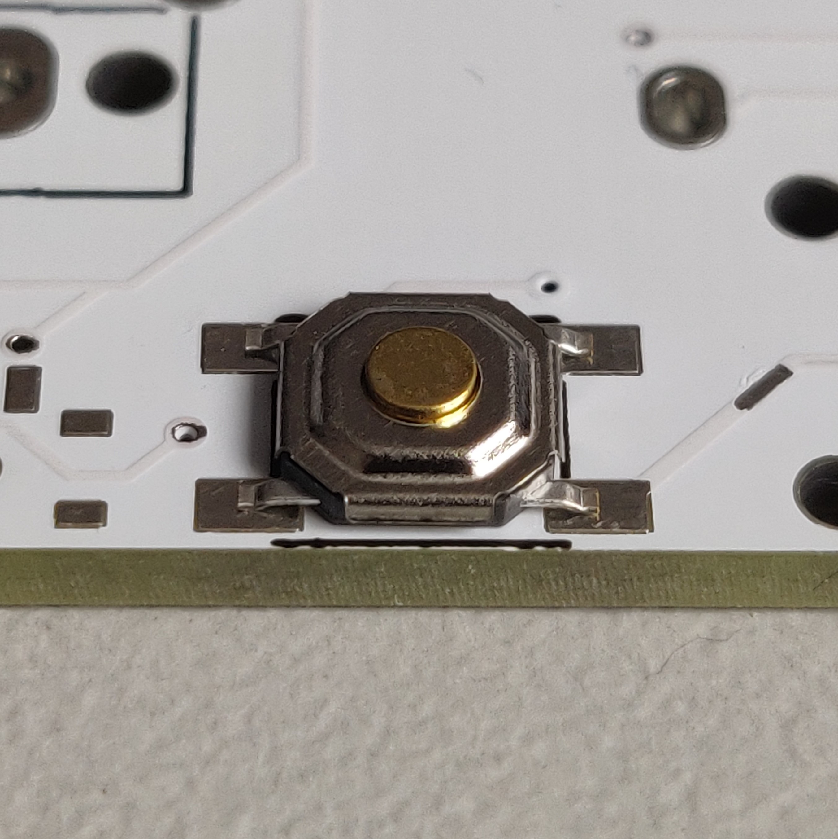 Add some solder to one of the pads of the reset switch footprint, on the top side of the PCB.
Place the reset switch on the footprint and solder the first leg.
Once the first leg is aligned correctly, solder the other three legs of the reset switch. Using tweezers will help you hold the switch in place without burning your fingers.
It should look like this:
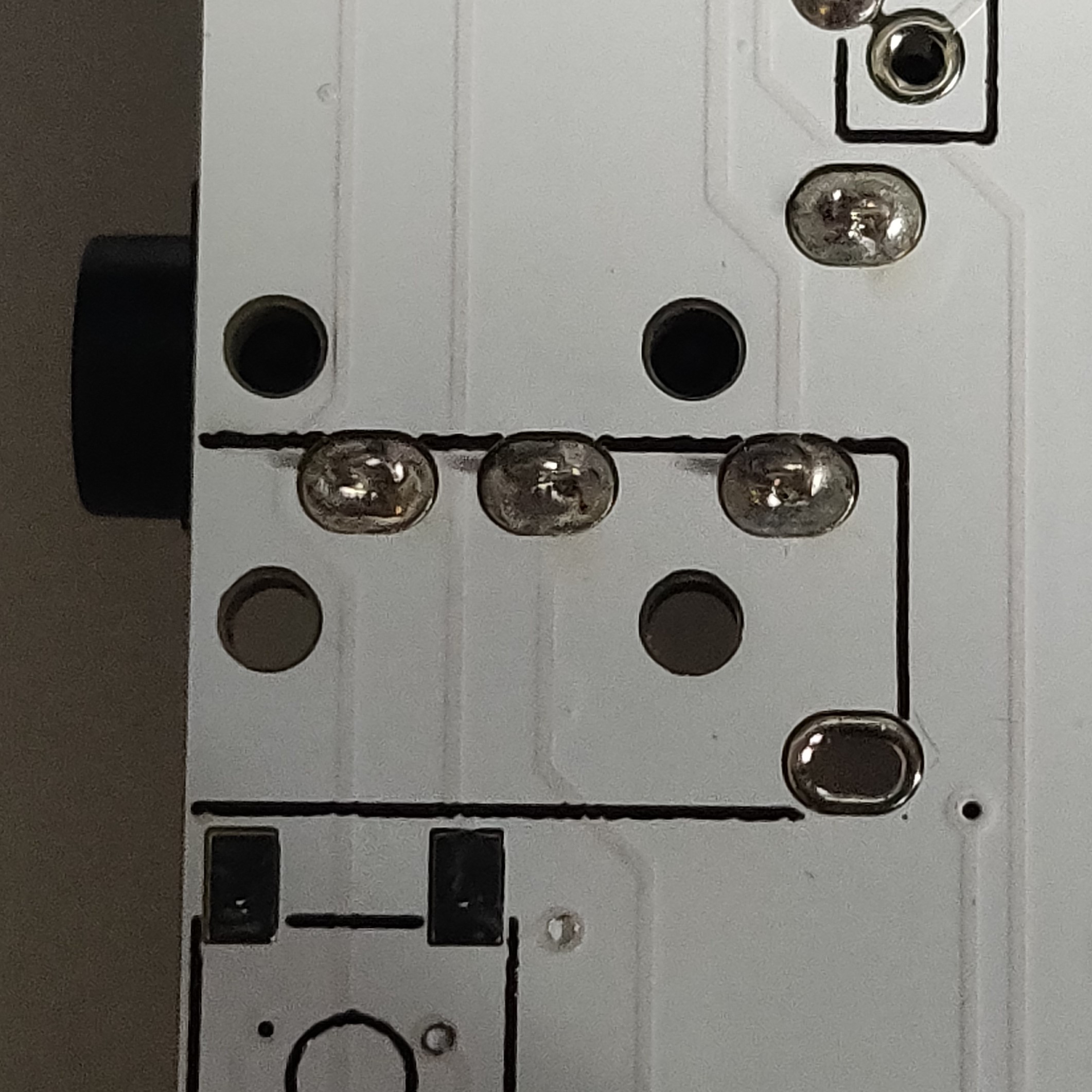
TRRS jacks
If you are using this build wirelessly, you can omit this step.
The TRRS jacks are soldered to the top side of the PCB.
Place the jack onto the outlined box on the PCB. The plastic legs should keep it in place.
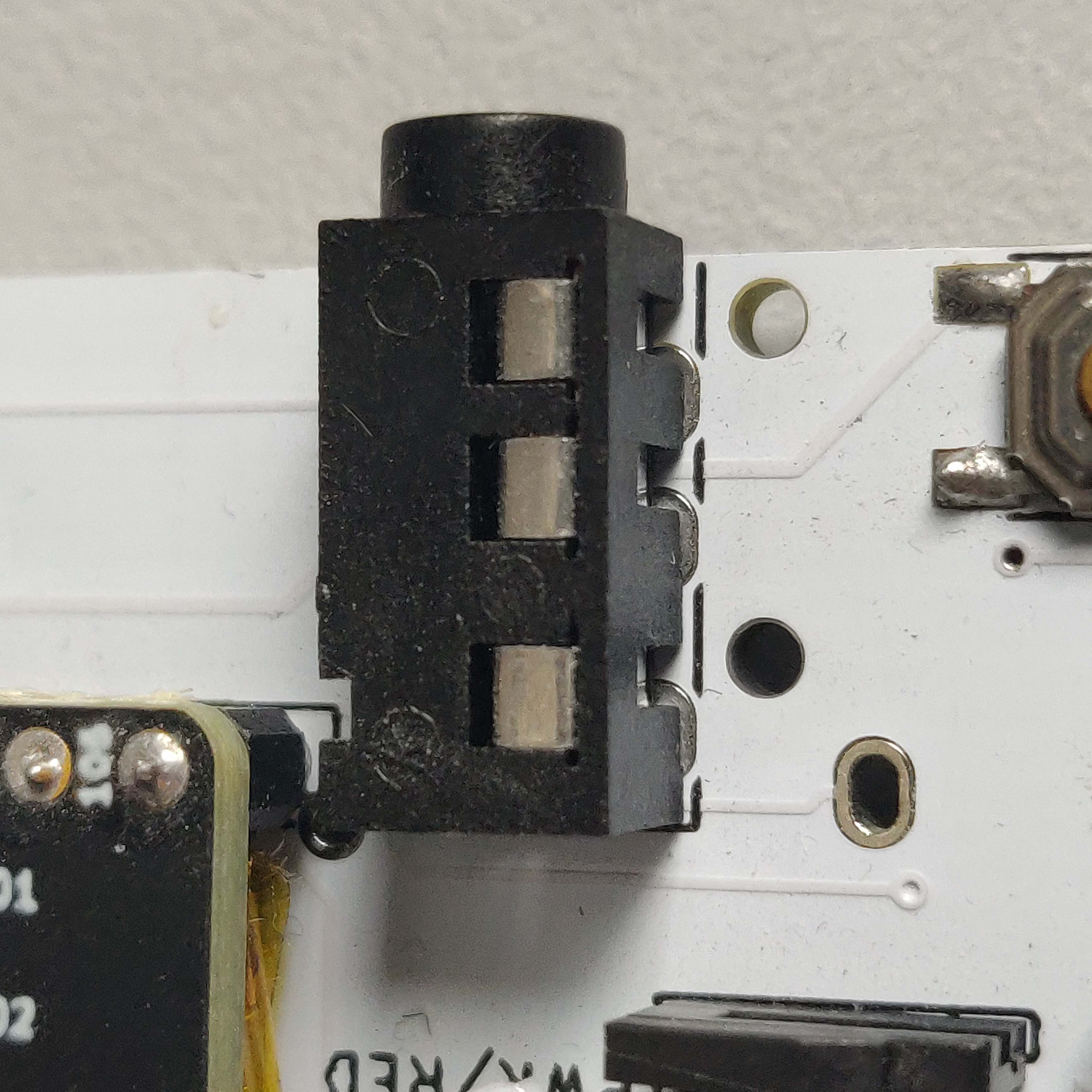
Solder the legs from the bottom of the PCB.
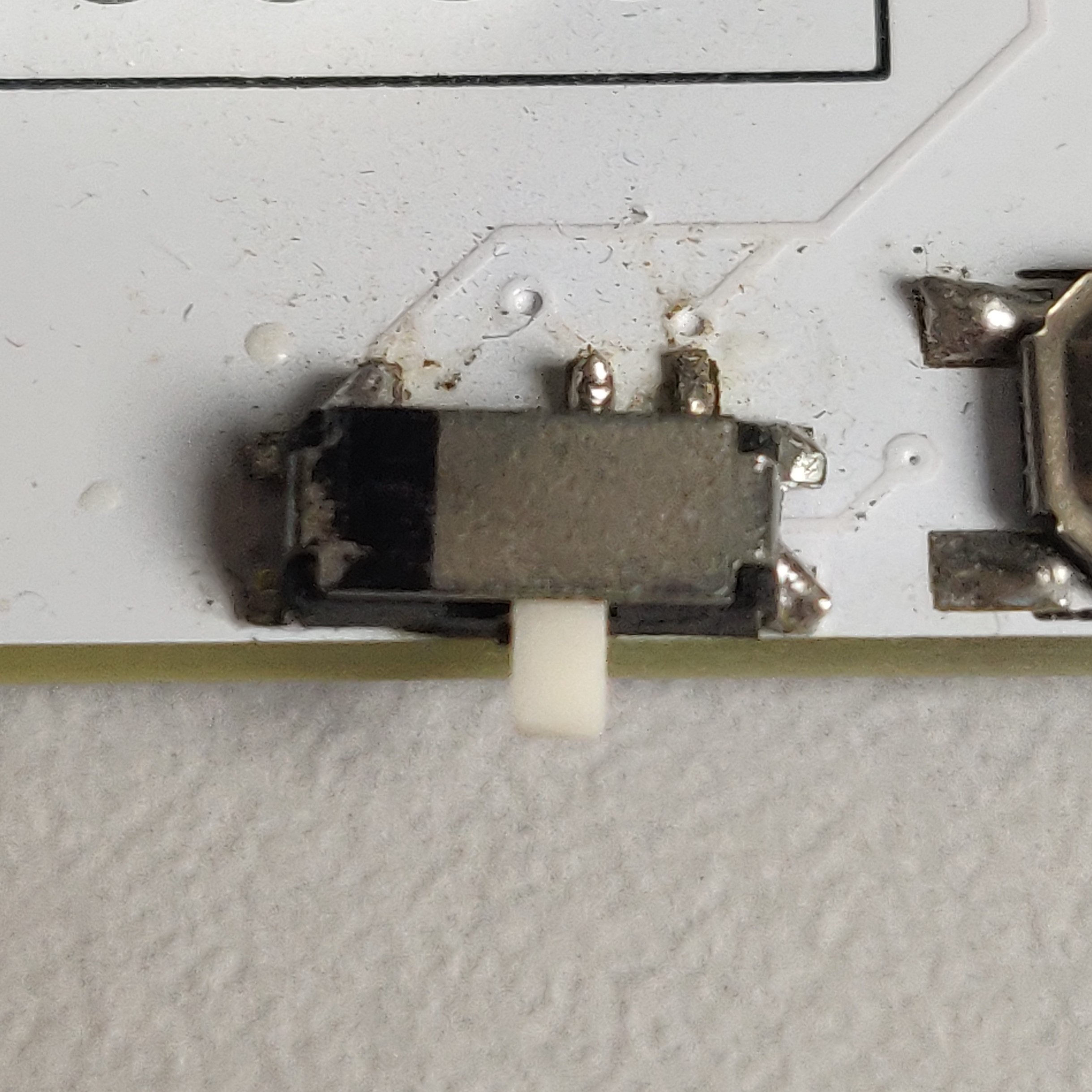
Power switches
If you are not using this build wirelessly, you can omit this step.
The power switches are soldered the same way as the reset switches.
Add some solder to one of the pads first, this will help you align the switch.
Once aligned, solder the rest of the legs of the switch.
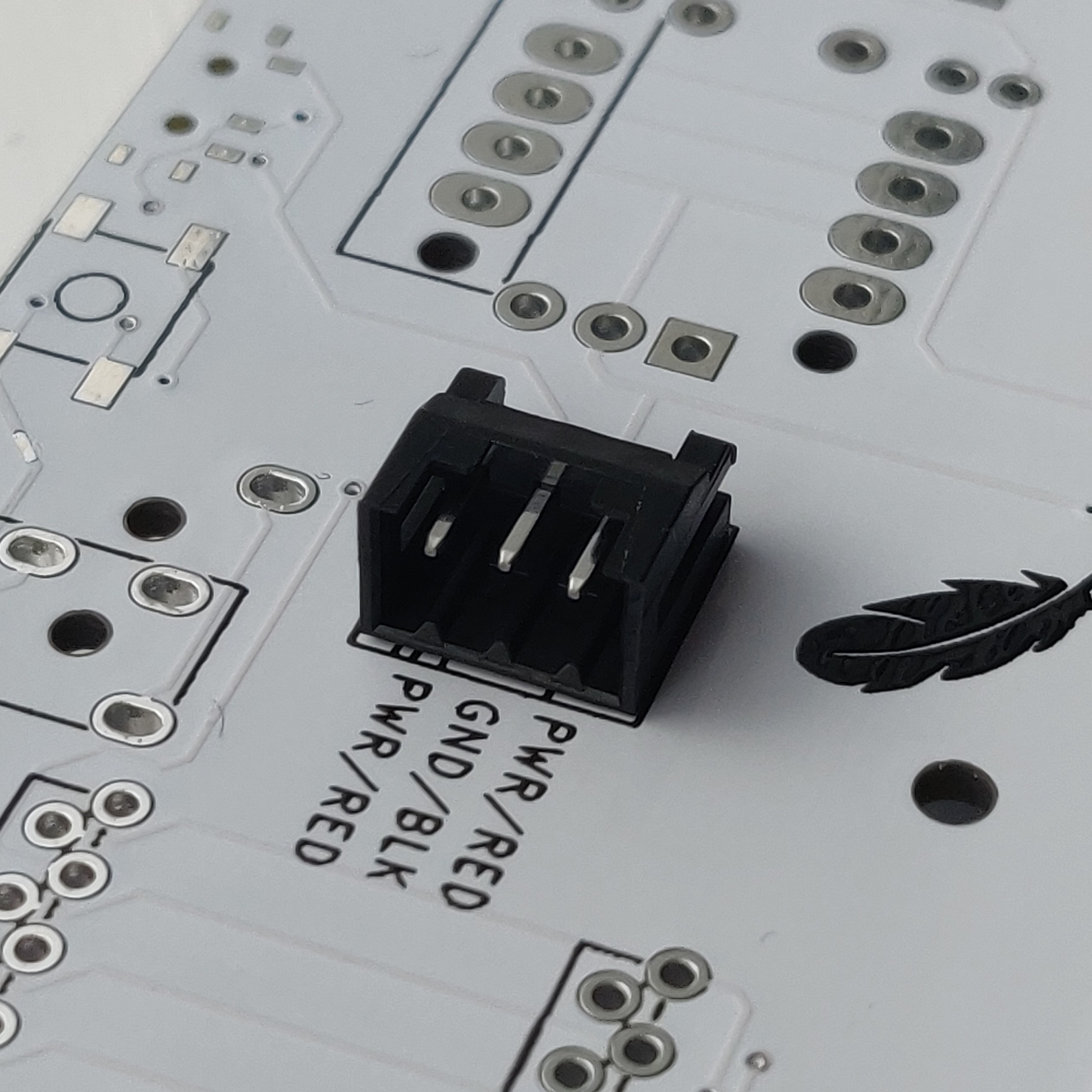
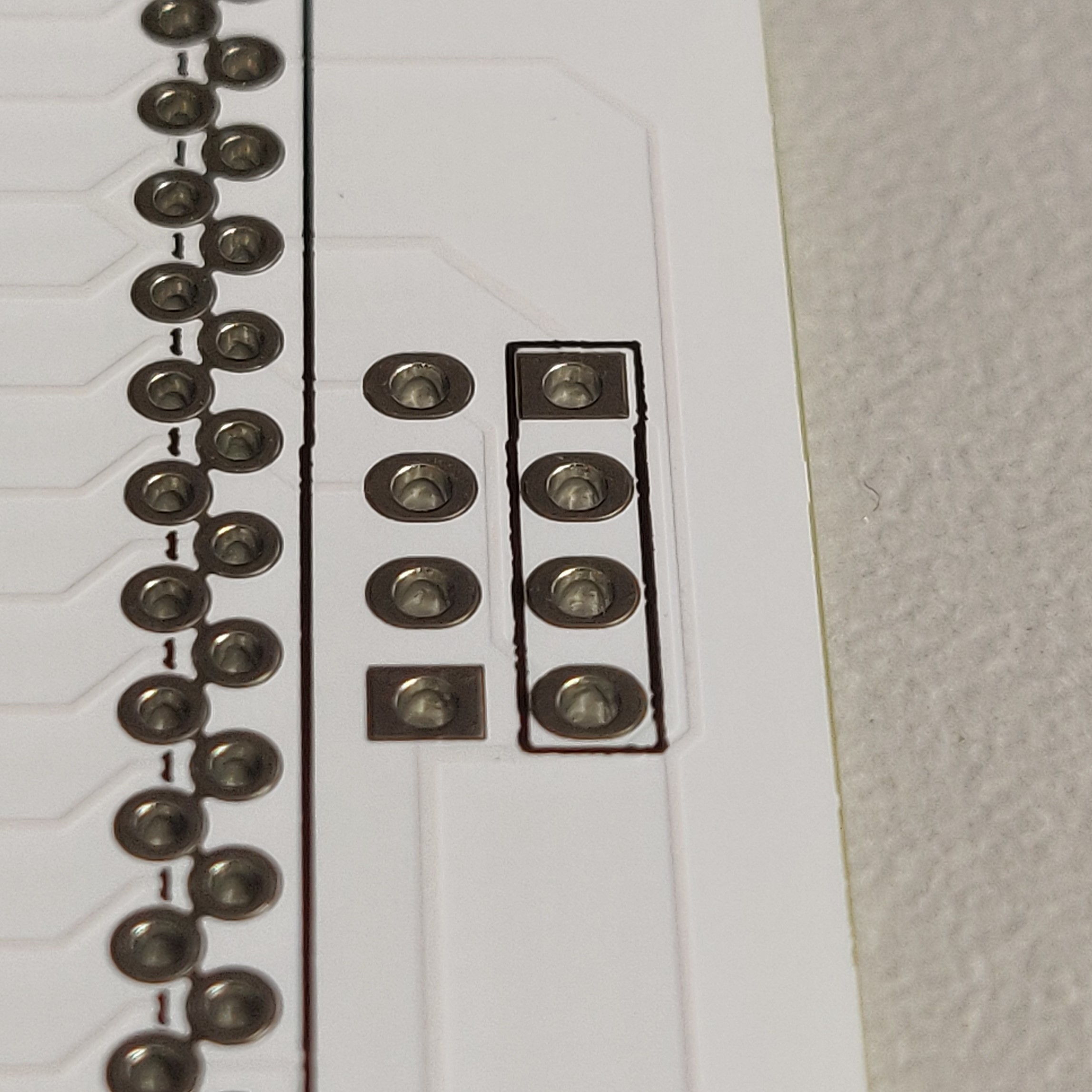
Battery connectors
If you are not using this build wirelessly, you can omit this step.
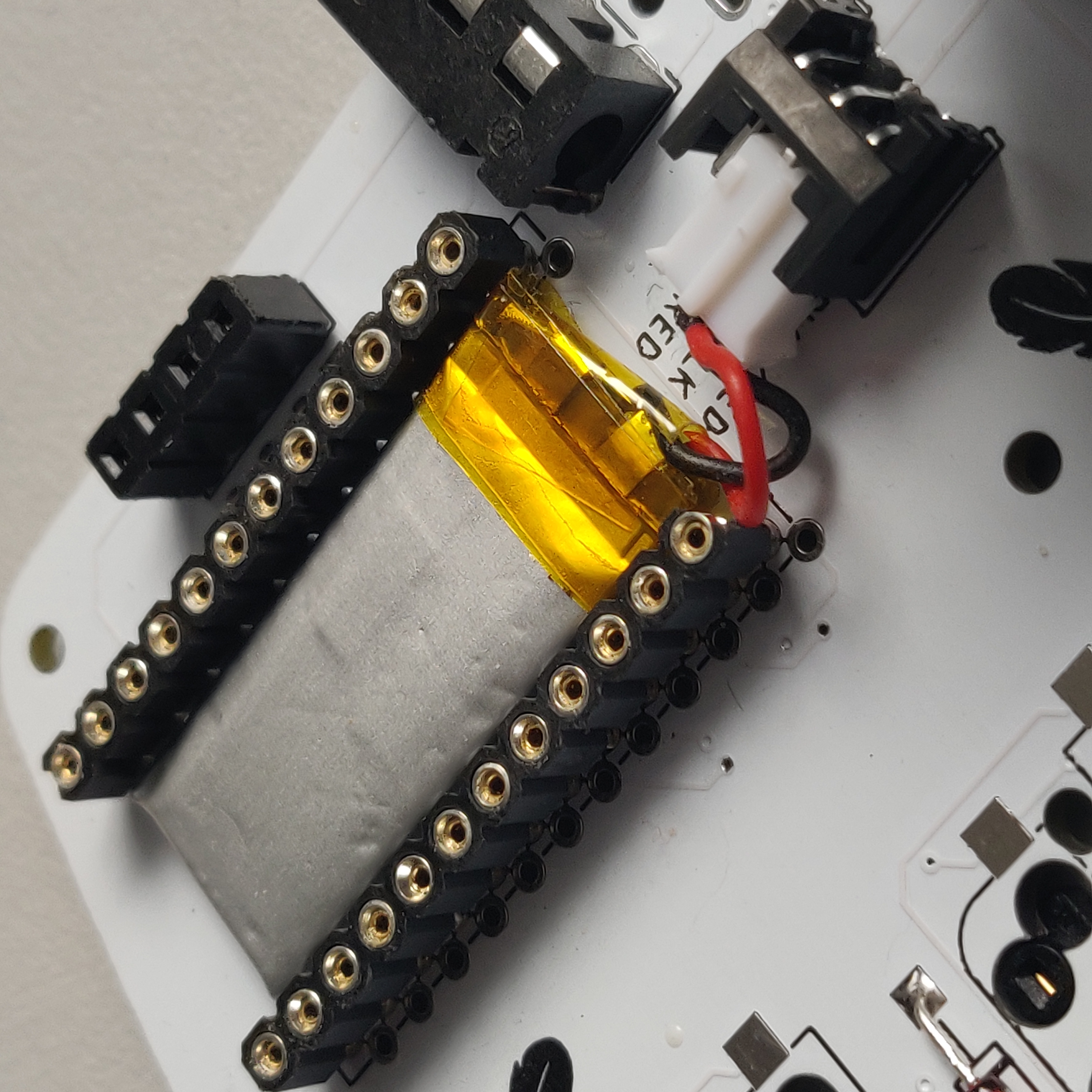
If you want to place a small battery under the micro controller, you’ll want to solder the battery connectors to the top side of the PCB.
Simply place the connector into the 3 holes and solder the legs from the other side.
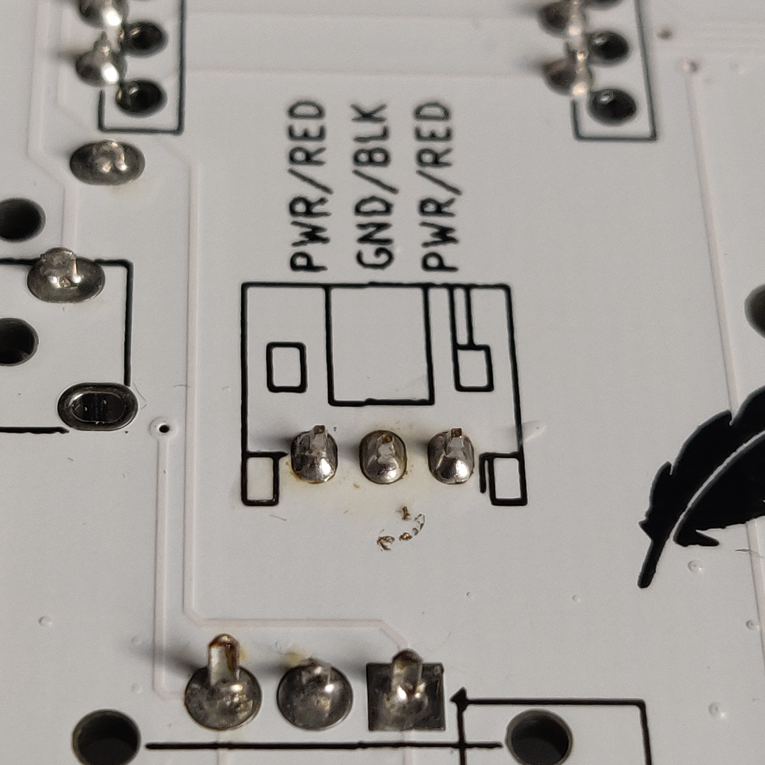
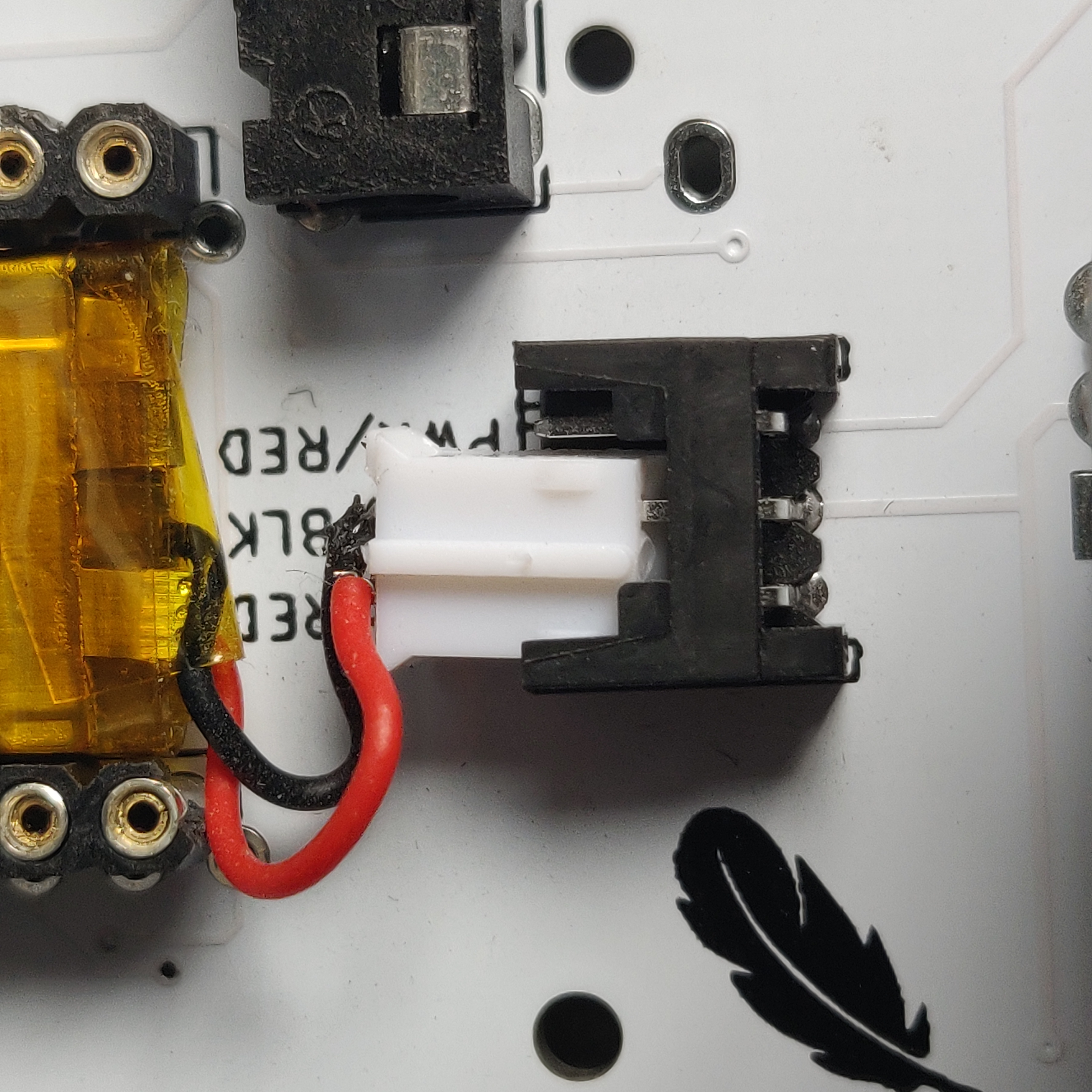
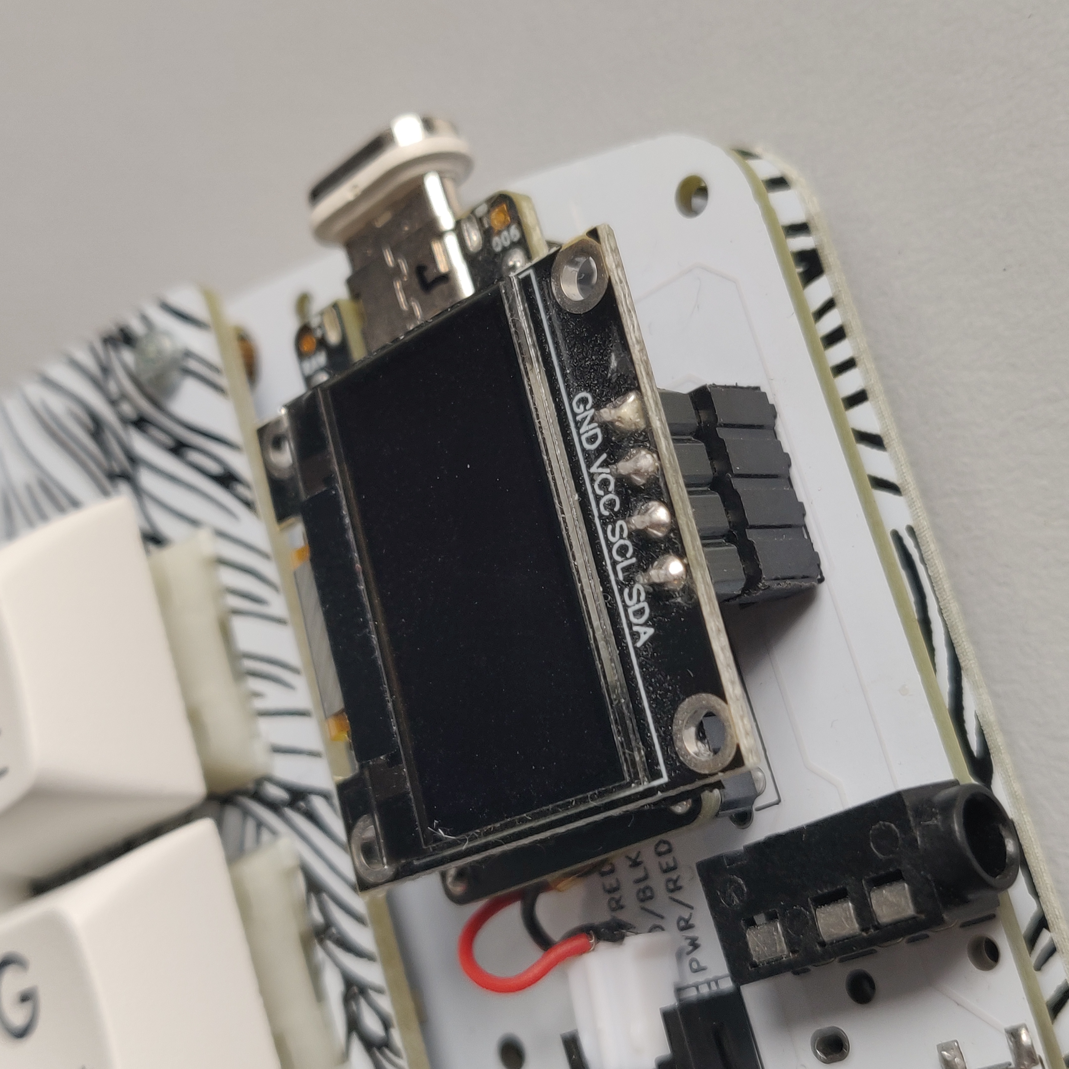
When connecting a battery, make sure that the JST connector of the battery is plugged in so that the red and black wires connect to the legs labelled as PWR/RED and GND/BLK on the PCB respectively. Getting this wrong could fry your micro controller!
 If you’re using a battery without a JST connector, you can solder the wires directly to the pads on the PCB. This is not recommended however as you could bridge the pads and short the battery - do so at your own risk!.
OLED sockets
Place the OLED sockets on the top side of the PCB in the footprint that is outlined with a black box.
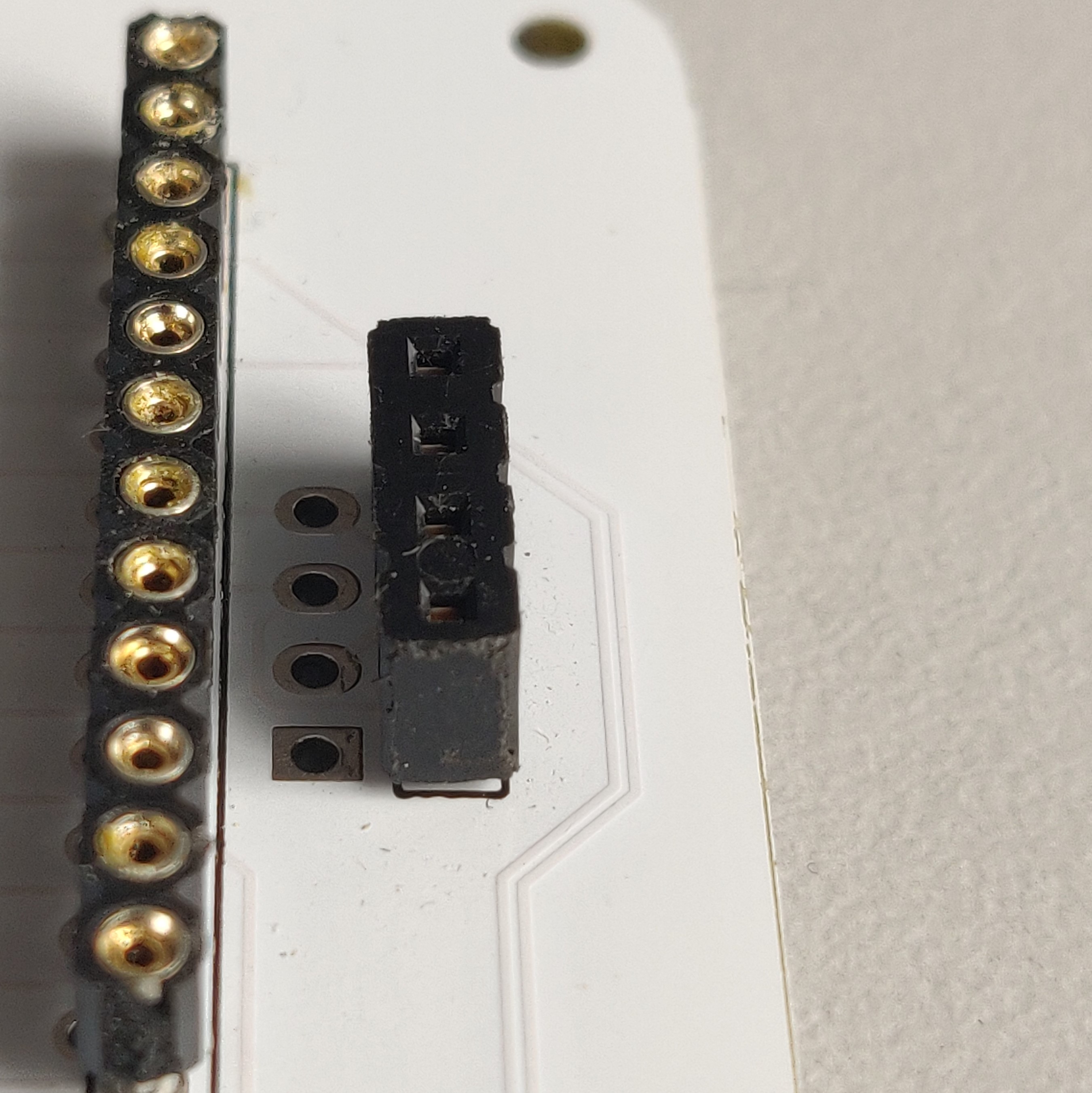
Solder the legs from the underside of the PCB.
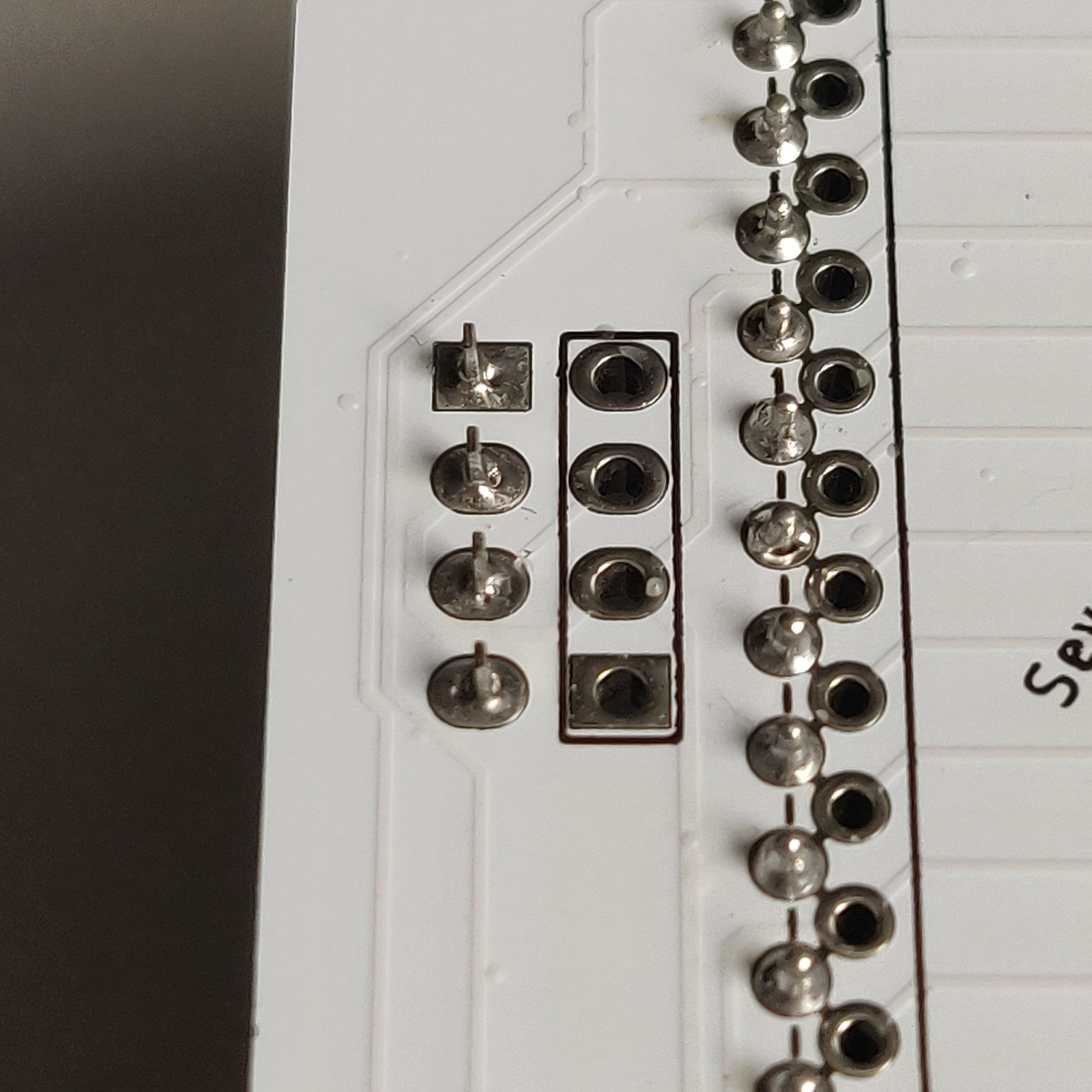
Microcontrollers
When connecting your microcontrollers to the PCB you may wish to socket them. I would recommend it, as the small amount of extra work required now saves you a lot of extra work later if you ever need to remove the controller.
To help you decide, read Why would I want to socket my microcontroller? by Splitkb
If you have decided to socket your microcontroller, follow How do I socket a microcontroller? by Splitkb.
You need to place the sockets within the black outline on the PCB, this means that you’ll be soldering on the other side of the keyboard, where the solder joints are not in a black outline.
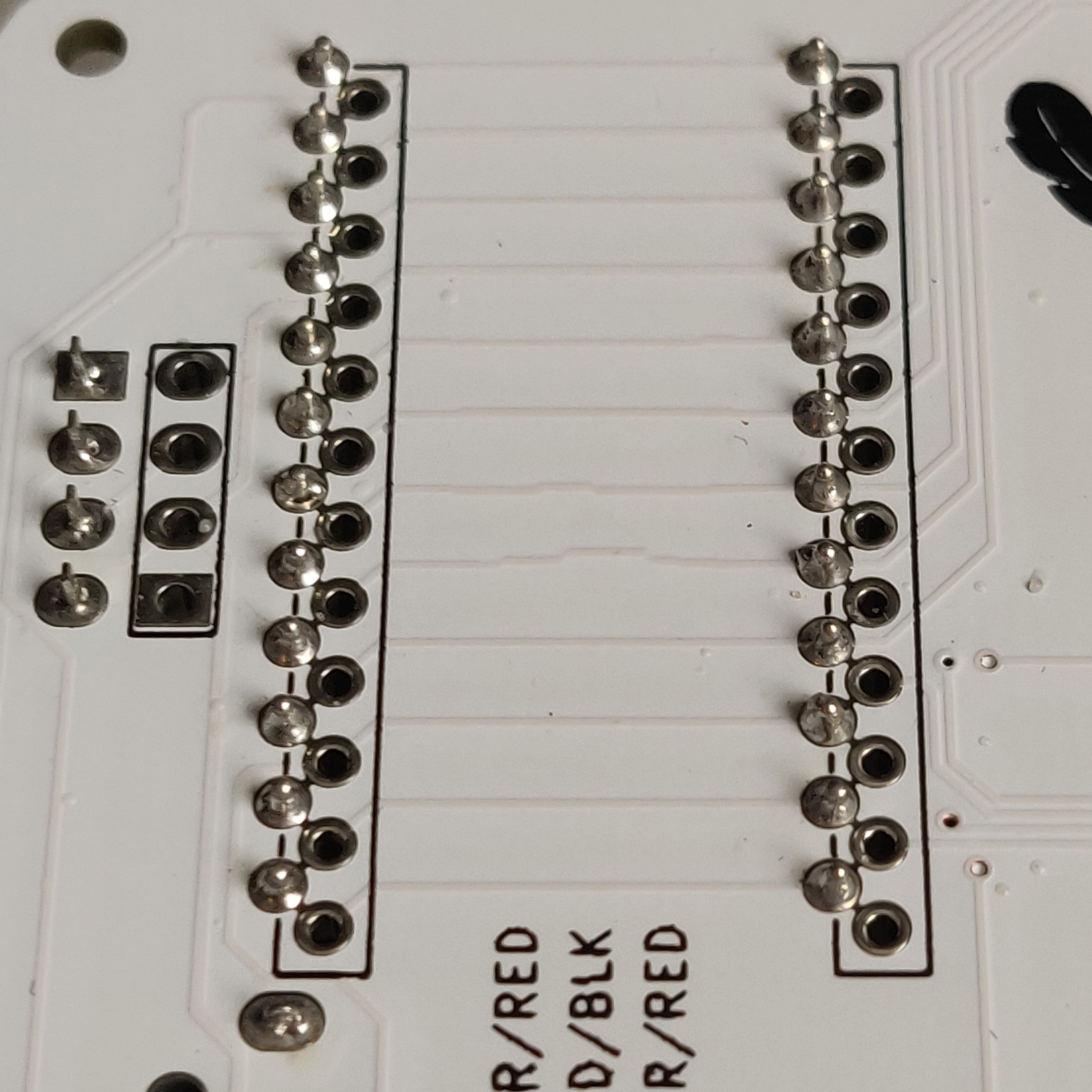
You must socket the microcontroller so that the components are face-down towards the PCB!
My preferred sockets are machine pin sockets as they give you enough space under the microcontroller to fit a 301230 battery.
I typically use Mill Max pins for socketing my controllers.
Your sockets should look like this:
Encoders
Both types of rotary encoder can go in either position on the keyboard. So you’ve got a total of 16 possible combinations.
Standard rotary encoders
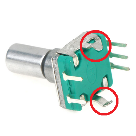
First you need to clip off the large legs from the encoder so that it sits flat against the PCB.
 Place the encoder on the top side of the PCB.
Solder the legs to the pads on the bottom of the PCB.
It should look like this:
Rollers
If you’ve bought a kit, the plastic hook on the bottom of the encoder should already be clipped.
If you have sourced the rollers yourself, you need to clip off the large plastic hook on the bottom of the encoder, this is so that it sits flat against the PCB.
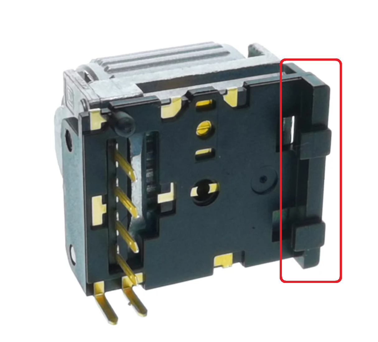
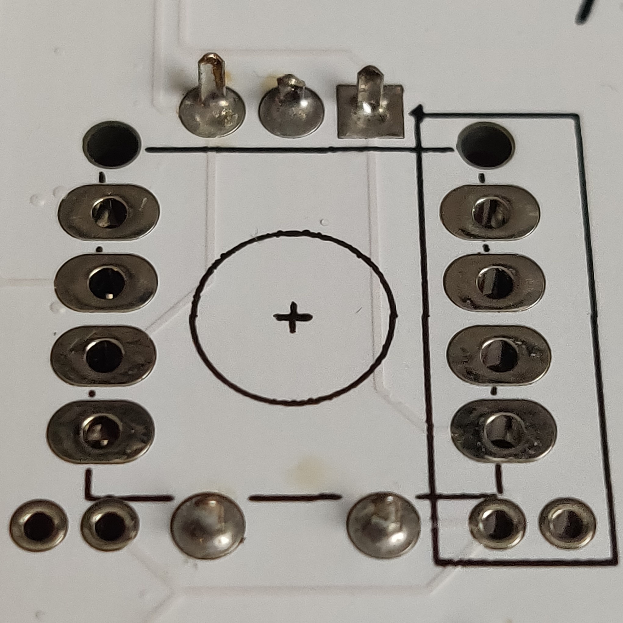
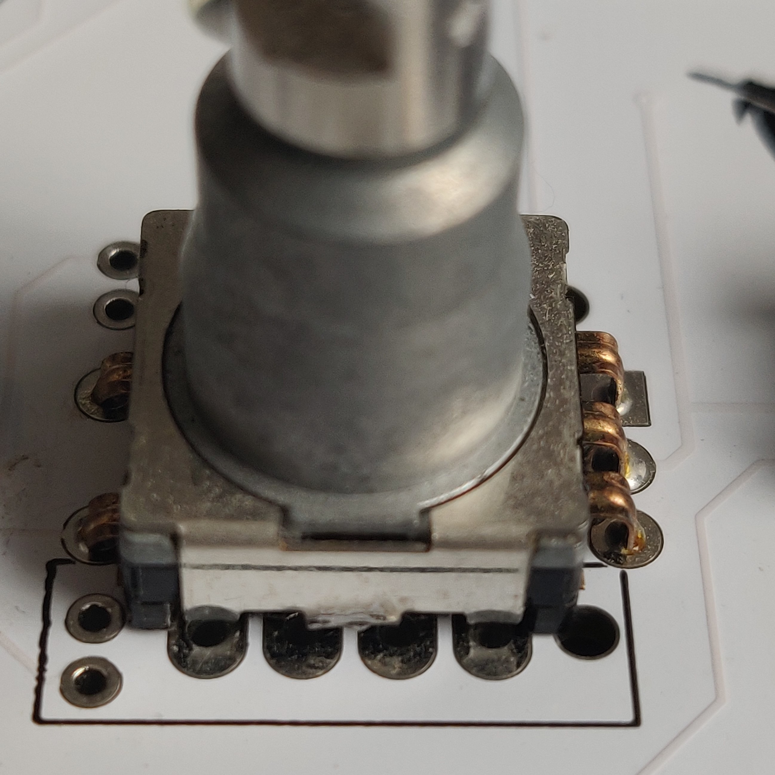
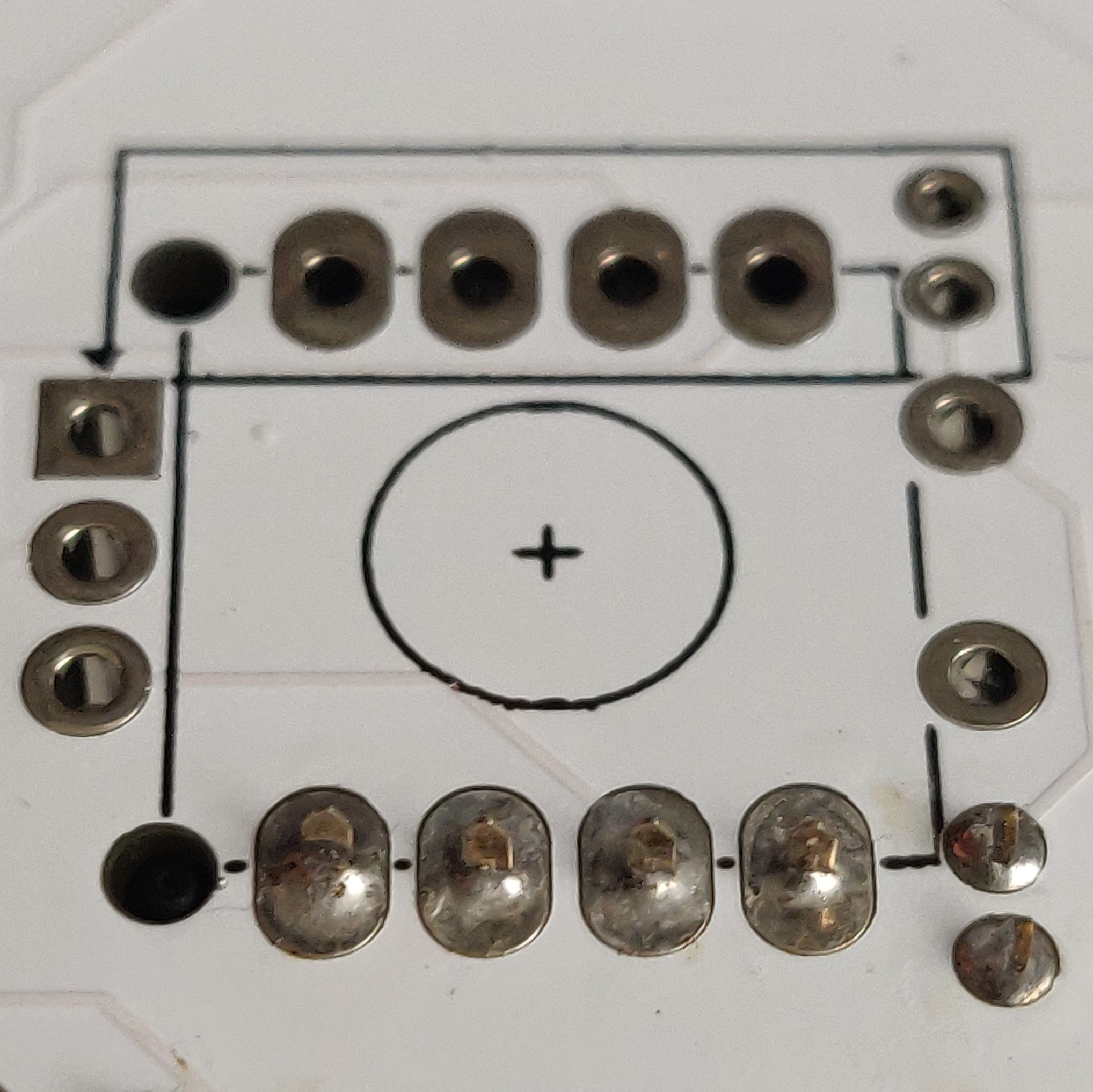
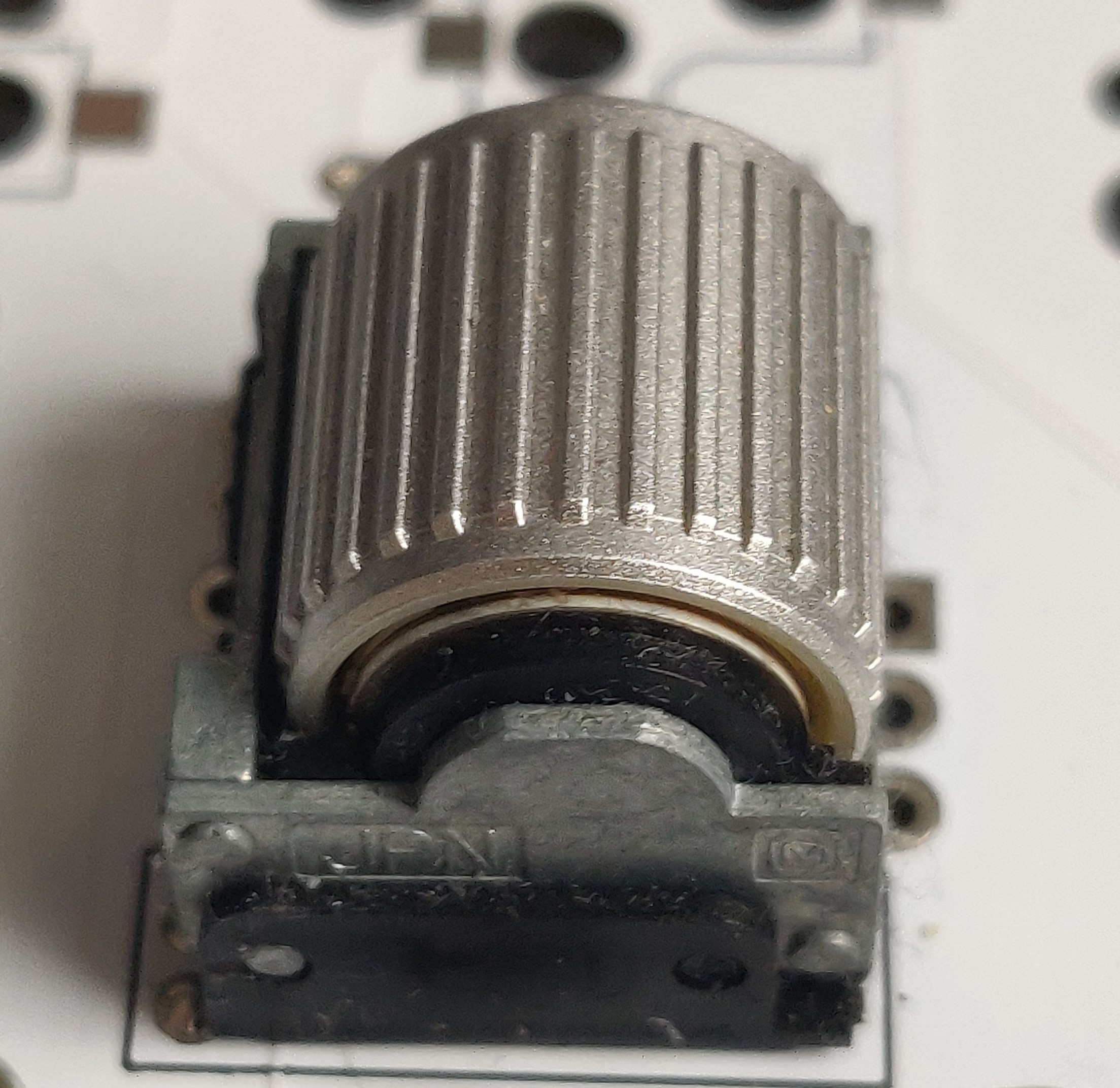
Align the encoder so that the legs pass through the pads surrounded by the black outline on the PCB.
Solder the legs from the bottom of the PCB.
It should look like this:
Assembly
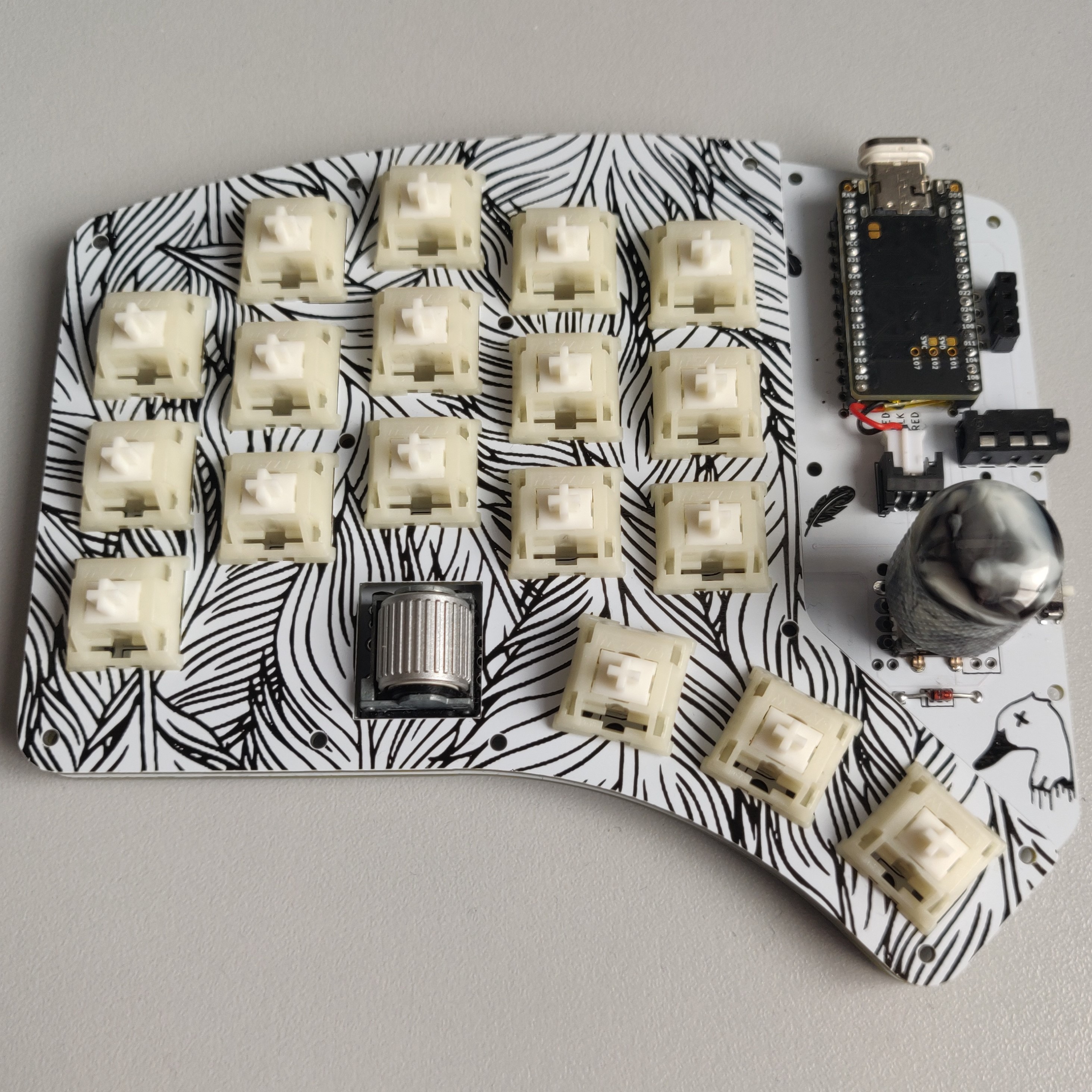
Now its time to put the board together!
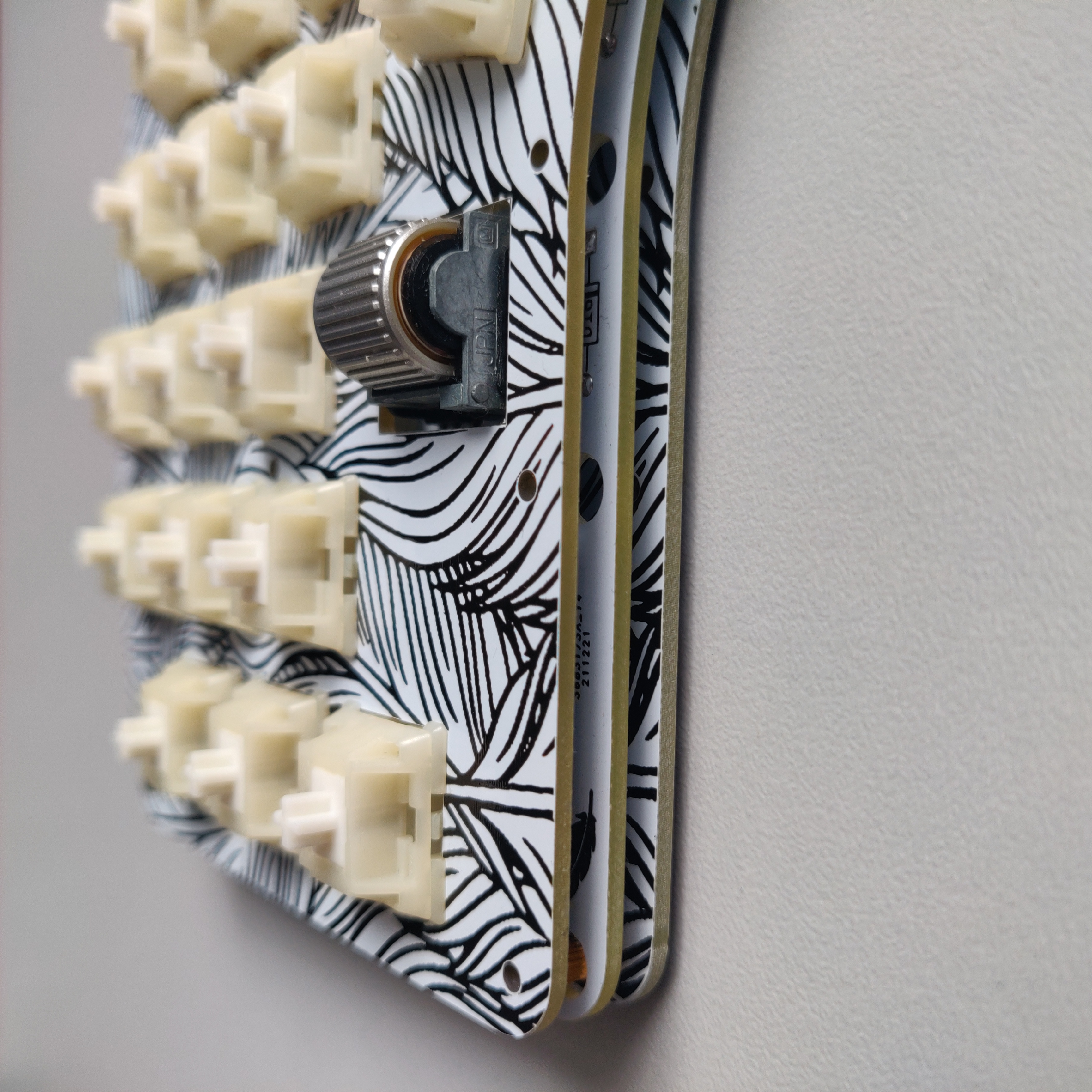
Begin by inserting your switches into the switch plate
 Then connect the switch plate to the PCB by pushing the switches into the hotswap sockets. Apply some pressure against the back of the hotswap sockets. If the solder connection isn’t strong there’s a chance they might be ripped off the PCB. I’ve never experienced this personally though.
 Now screw the standoffs into the bottom plate. You don’t have to use all of them. The more you use, the more rigid the typing experience will be. I prefer to use 5 per half.
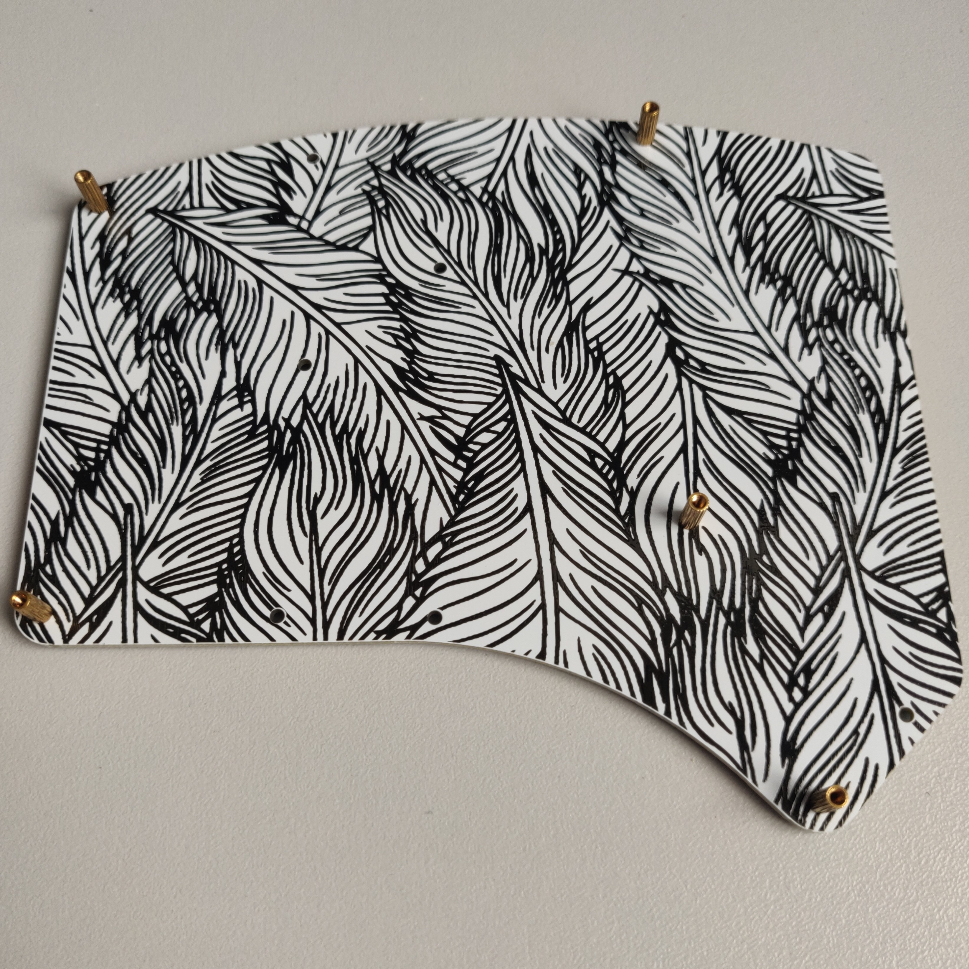 Now place your PCB and switch plate combo on top of the bottom plate. Aligning the holes in the PCB with the standoffs.
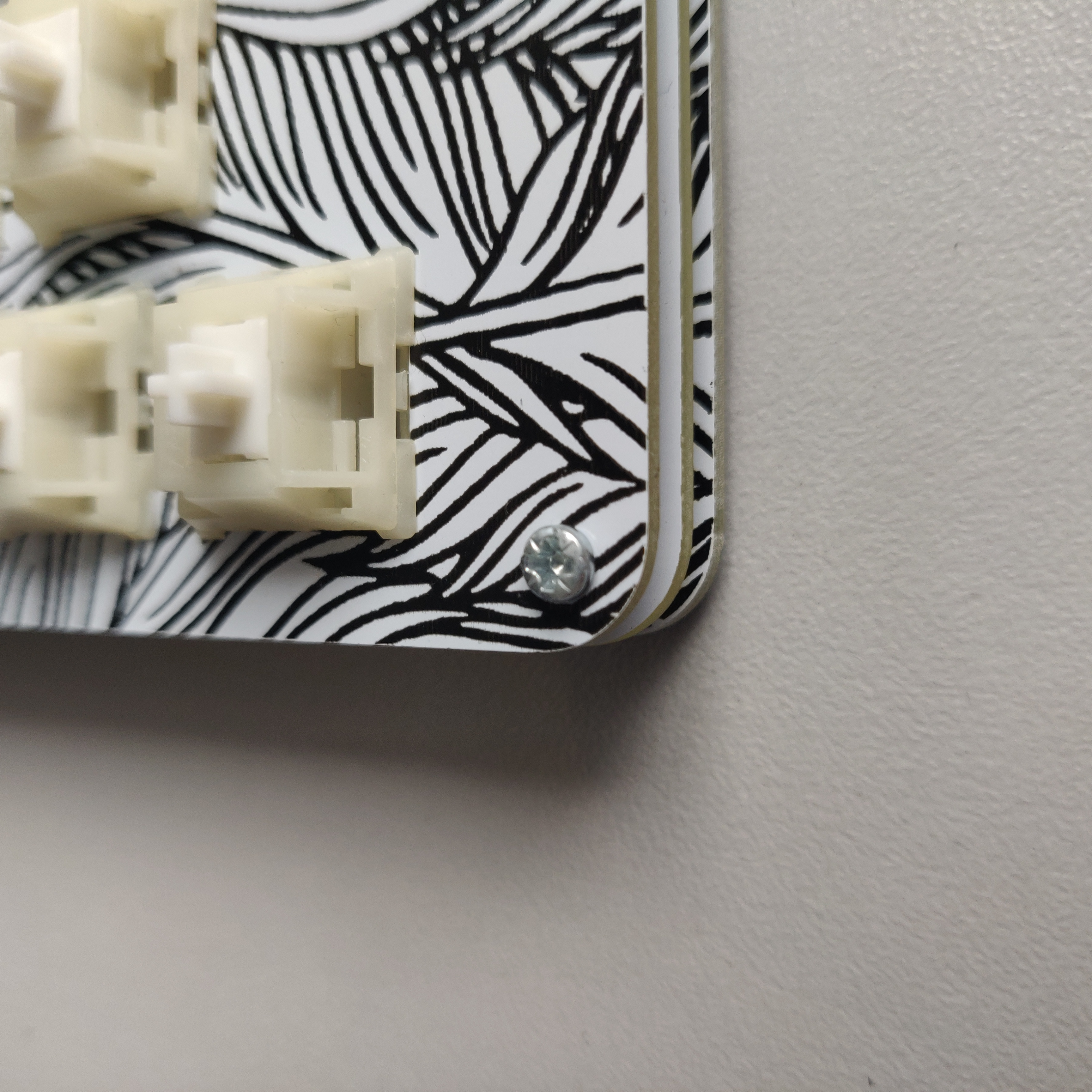
 From the top of the switch plate you can now screw into the standoffs, securing the 3 layer stack.
 Add your rubber feet to the underside of the bottom plate.
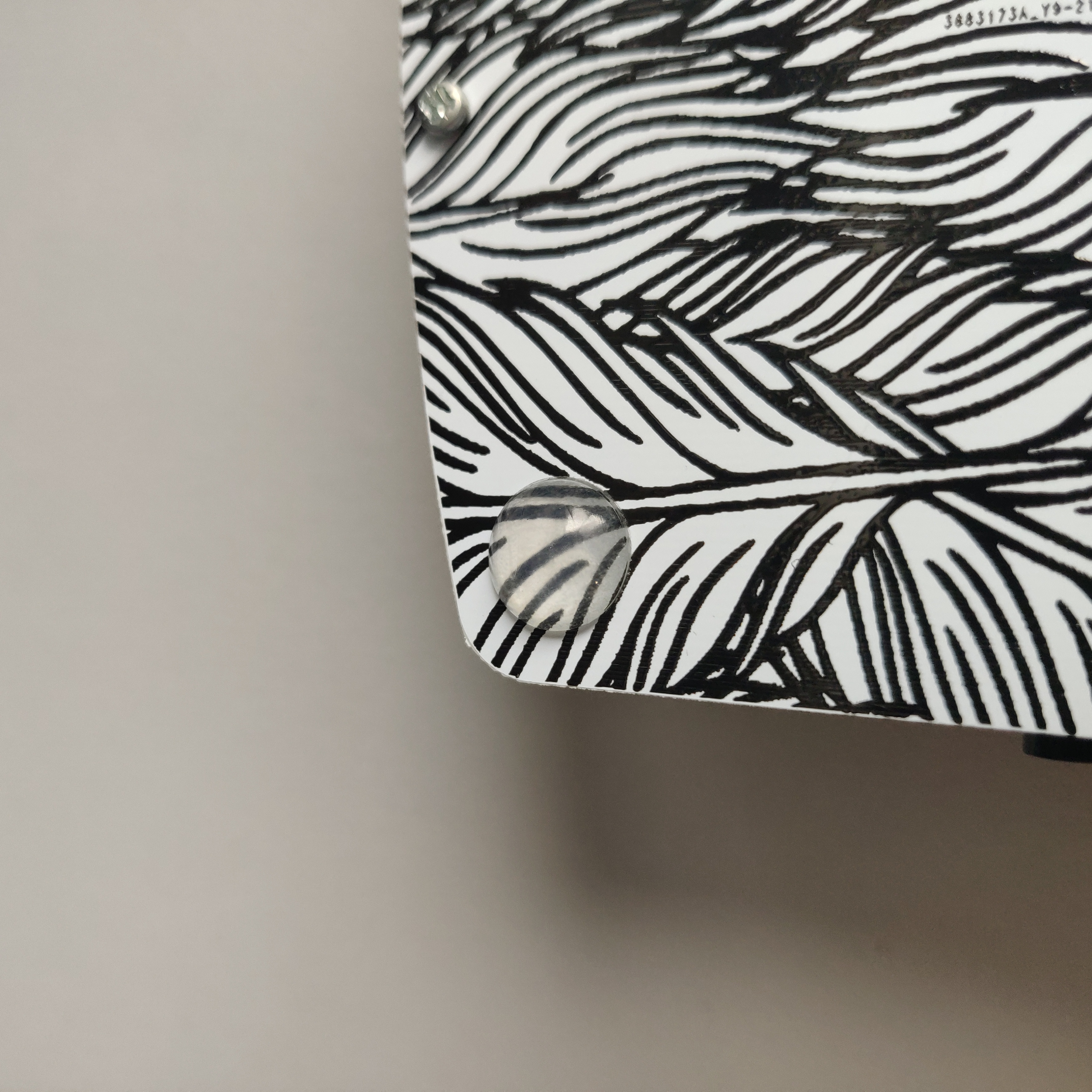 Finally insert the OLED displays into the sockets and push on your keycaps.
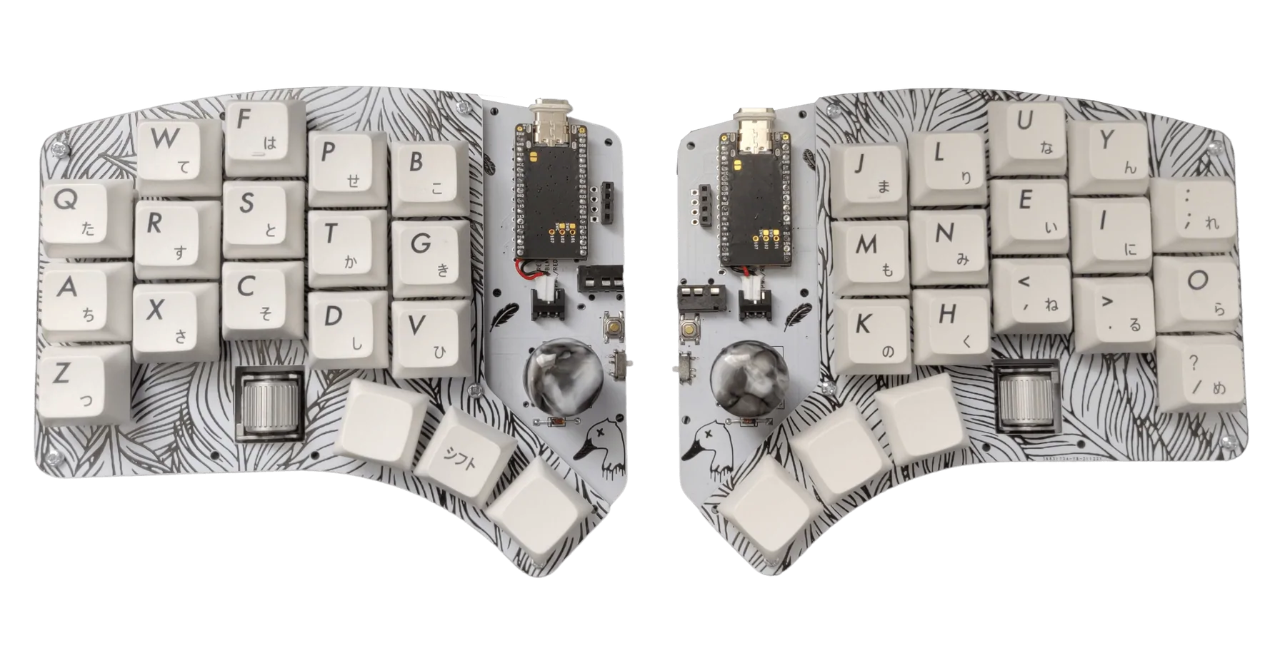
 You should now have a fully assembled Waterfowl keyboard!
Firmware
Your final step to complete your Waterfowl build is to flash the microcontrollers with your chosen firmware.
For a guide to flash QMK firmware click here.
For a guide to flash ZMK firmware click here.
If you wish to use Vial (a GUI application for your keymap) click here.